1GD-FTV INTAKE / EXHAUST EXHAUST MANIFOLD W/ TURBOCHARGER REMOVAL
PROCEDURE

 1.DISCONNECT CABLE FROM NEGATIVE BATTERY TERMINAL
- NOTICE:
-
When disconnecting the cable, some systems need to be initialized after the cable is reconnected (See page ).
-
Click hereGeneral>INTRODUCTION>REPAIR INSTRUCTION>INITIALIZATION
25051
2.REMOVE EXHAUST MANIFOLD CONVERTER SUB-ASSEMBLY
3.DRAIN ENGINE COOLANT
4.DRAIN ENGINE OIL
17341K
5.REMOVE INTERCOOLER AIR HOSE
17342F
6.REMOVE NO. 2 INTERCOOLER AIR HOSE
44306
7.DISCONNECT VANE PUMP OIL RESERVOIR SUB-ASSEMBLY
16571C
8.REMOVE NO. 1 RADIATOR HOSE
16470
9.REMOVE RADIATOR RESERVOIR ASSEMBLY
82123
10.DISCONNECT NO. 3 ENGINE WIRE (for Cold Area Specification Vehicles)
16711
11.REMOVE FAN SHROUD
17705
12.REMOVE AIR CLEANER CAP SUB-ASSEMBLY WITH AIR CLEANER HOSE
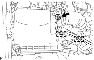
Disconnect the mass air flow meter sub-assembly connector and detach the 2 harness clamps.
Detach the 4 clips.
Loosen the hose clamp and remove the air cleaner cap sub-assembly with air cleaner hose.
17801
13.REMOVE AIR CLEANER FILTER ELEMENT SUB-ASSEMBLY
Remove the air cleaner element sub-assembly from the air cleaner case.
14.REMOVE AIR CLEANER CASE SUB-ASSEMBLY
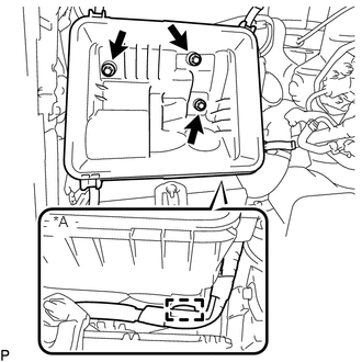
| *A | for Cold Area Specification Vehicles |
Remove the 3 bolts and air cleaner case sub-assembly.
87120G
15.DISCONNECT VISCOUS WITH MAGNET CLUTCH HEATER ASSEMBLY (for Cold Area Specification Vehicles)
87209B
16.REMOVE WATER HOSE SUB-ASSEMBLY B (w/ Viscous Heater)
16279
17.REMOVE NO. 3 WATER BY-PASS PIPE
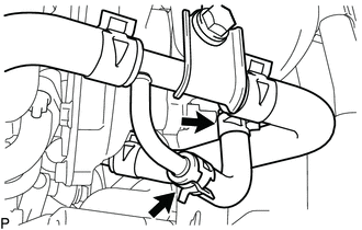
for Cold Area Specification Vehicles:
Slide the 2 clips and remove the water hose from the compressor inlet elbow and No. 3 water by-pass pipe.
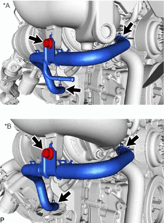
| *A | for Cold Area Specification Vehicles |
| *B | except Cold Area Specification Vehicles |
Slide the 2 clips and disconnect the 2 water hoses from the oil cooler assembly and No. 2 water bypass pipe.
Remove the bolt and No. 3 water by-pass pipe.
12229
18.REMOVE PCV PIPE (for Cold Area Specification Vehicles)
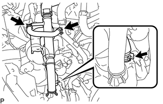
Slide the 2 clips and disconnect the No. 20 water by-pass hose from the compressor inlet elbow and No. 3 water by-pass pipe.
Slide the clip and disconnect the No. 19 water bypass hose from the compressor inlet elbow.
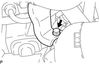
Remove the bolt and disconnect the PCV pipe from the compression inlet elbow.
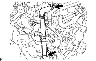
Slide the 2 clips and remove the PCV pipe.
12261
19.REMOVE PCV HOSE (except Cold Area Specification Vehicles)
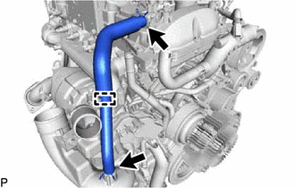
Slide the 2 clips.
Slide the 2 clips, detach the clamp and remove the PCV hose.
16268
20.REMOVE NO. 1 WATER BY-PASS PIPE
16284
21.DISCONNECT TURBO WATER HOSE
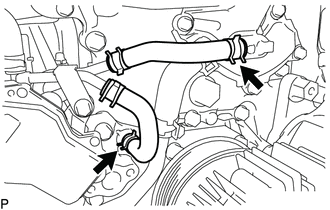
Slide the 2 clips and disconnect the No. 1 turbo water hose and No. 2 turbo water hose from the water outlet sub-assembly and water pump assembly.
22.REMOVE OIL COOLER TUBE BRACKET AND WIREHARNESS CLAMP BRACKET
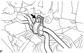
for Automatic Transmission:
Remove the bolt and disconnect the oil cooler tube bracket.
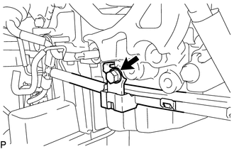
Remove the bolt and disconnect the wire harness.
87101
23.DISCONNECT NO. 1 VISCOUS HEATER BRACKET SUB-ASSEMBLY (for Cold Area Specification Vehicles)
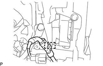
Remove the detach the clamp and disconnect the wire harness.
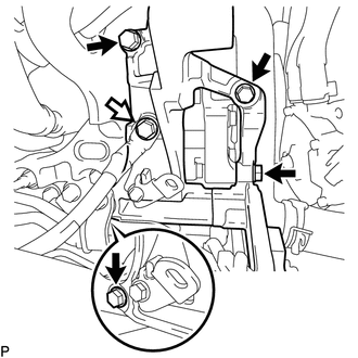

|
No. 1 Viscous Heater Bracket Sub-assembly Bolt |

|
No. 4 Engine Harness Bolt |
Remove the bolt and disconnect the No. 4 engine harness.
Remove the 4 bolts and No. 1 viscous heater bracket sub-assembly.
17293
24.REMOVE TURBOCHARGER STAY
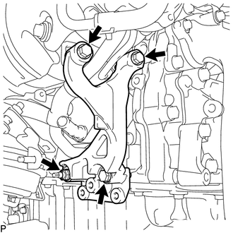
for Type A:
Remove the 3 bolts and nut.
Using an E8 "TORX" socket wrench, remove the stud bolt and turbocharger stay.
for Type B:
Remove the 3 bolts, nut and the turbocharger stay.
15474
25.REMOVE TURBO OIL OUTLET PIPE
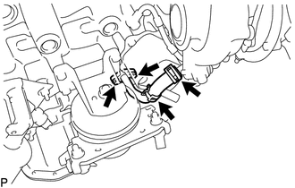
Slide the 2 clips and disconnect the turbo oil outlet hose from the turbo oil outlet pipe.
except Cold Area Specification Vehicles and w/ Cover
Remove the cover from the turbo oil outlet pipe.
Remove the 2 bolts and turbo oil outlet pipe and gasket.
15407
26.REMOVE TURBO OIL INLET PIPE SUB-ASSEMBLY
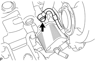
Remove the union bolt and gasket.
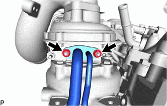
Remove the 2 nuts and the turbo oil inlet pipe subassembly.
- NOTICE:
-
Do not loosen the nut labeled A.
Remove the gasket.
17201
27.REMOVE TURBOCHARGER SUB-ASSEMBLY
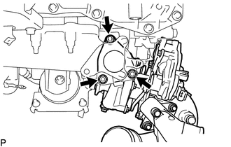
Remove the 3 nuts and turbocharger sub-assembly.
Remove the gasket from the exhaust manifold.
25601
28.DISCONNECT NO. 1 EGR PIPE SUB-ASSEMBLY
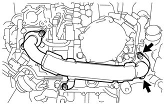
Remove the 2 nuts and disconnect the No. 1 EGR pipe sub-assembly.
17141
29.REMOVE EXHAUST MANIFOLD
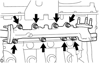
Remove the 8 nuts, 8 plate washers, 8 collars and exhaust manifold.
Remove the 2 gaskets (cylinder head side and No. 1 EGR pipe sub-assembly side).
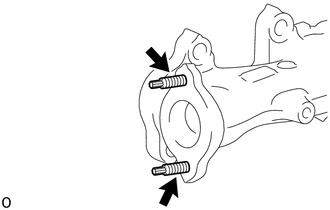
Using an E8 "TORX" socket wrench, remove the 2 stud bolts from the exhaust manifold.
16027
30.REMOVE NO. 1 TURBO WATER PIPE SUB-ASSEMBLY
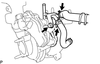
Slide the 2 hose clips and disconnect the No. 1 turbo water hose and No. 2 turbo water hose from the turbo water pipe sub-assembly.
Remove the bolt.
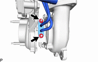
Remove the 2 nuts, turbo water pipe sub-assembly and gasket.
17274
31.REMOVE COMPRESSOR INLET ELBOW
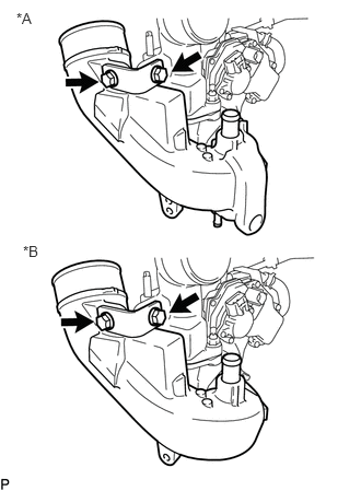
| *A | for Cold Area Specification Vehicles |
| *B | except Cold Area Specification Vehicles |
Remove the 2 bolts and compressor inlet elbow stay.
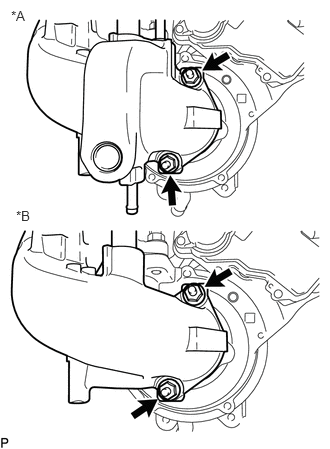
| *A | for Cold Area Specification Vehicles |
| *B | except Cold Area Specification Vehicles |
Remove the 2 nuts and compressor inlet elbow from turbocharger sub-assembly.
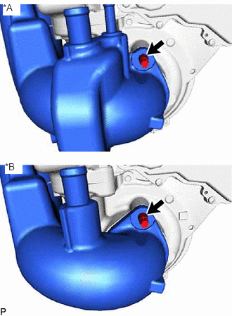
| *A | for Cold Area Specification Vehicles |
| *B | except Cold Area Specification Vehicles |
Using an E8 "TORX" socket wrench, remove the stud bolt shown in the illustration together with the compressor inlet elbow and gasket.
17275
32.REMOVE COMPRESSOR OUTLET ELBOW
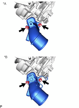
| *A | for Cold Area Specification Vehicles |
| *B | except Cold Area Specification Vehicles |
Remove the 2 nuts and compressor outlet elbow.
Remove the gasket.
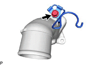
except Cold Area Specification Vehicles:
Remove the bolt and hose clamp
33.DISCONNECT STUD BOLT
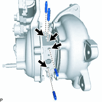
Using an E5 "TORX" socket wrench, remove the 4 stud bolts shown in the illustration.
- NOTICE:
-
If a stud bolt is deformed or its threads are damaged, replace it.
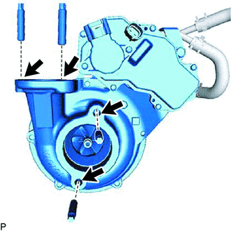
Using an E8 "TORX" socket wrench, remove the 4 stud bolts shown in the illustration.
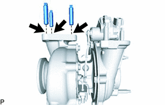
Using an E10 "TORX" socket wrench, remove the 3 stud bolts shown in the illustration.