SUSPENSION CONTROL AIR SUSPENSION SYSTEM C1731 FR Damping Force Control Actuator Circuit C1732 FL Damping Force Control Actuator Circuit C1733 RR Damping Force Control Actuator Circuit C1734 RL Damping Force Control Actuator Circuit
DESCRIPTION
The absorber control actuator switches the damping force depending on the suspension control ECU signals.
| DTC Code | DTC Detection Condition | Trouble Area |
|---|---|---|
| C1731 | Either condition is met:
·
An actuator open-circuit signal is detected for at least 1 second when the actuator operates. ·
An actuator short-circuit signal is consecutively detected 8 times when the actuator operates. |
·
Harness or connector ·
Front absorber control actuator RH ·
Suspension control ECU |
| C1732 | Either condition is met:
·
An actuator open-circuit signal is detected for at least 1 second when the actuator operates. ·
An actuator short-circuit signal is consecutively detected 8 times when the actuator operates. |
·
Harness or connector ·
Front absorber control actuator LH ·
Suspension control ECU |
| C1733 | Either condition is met:
·
An actuator open-circuit signal is detected for at least 1 second when the actuator operates. ·
An actuator short-circuit signal is consecutively detected 8 times when the actuator operates. |
·
Harness or connector ·
Rear absorber control actuator RH (Rear shock absorber assembly) ·
Suspension control ECU |
| C1734 | Either condition is met:
·
An actuator open-circuit signal is detected for at least 1 second when the actuator operates. ·
An actuator short-circuit signal is consecutively detected 8 times when the actuator operates. |
·
Harness or connector ·
Rear absorber control actuator LH (Rear shock absorber assembly) ·
Suspension control ECU |
WIRING DIAGRAM
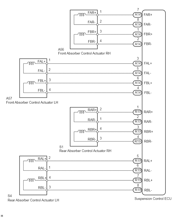
CAUTION / NOTICE / HINT
- NOTICE:
-
When replacing the suspension control ECU, perform registration (See page Suspension>SUSPENSION CONTROL>AIR SUSPENSION SYSTEM>REGISTRATION).
PROCEDURE
Turn the ignition switch off.
Connect the GTS to the DLC3.
Turn the ignition switch to ON.
Turn the GTS on.
Enter the following menus: Chassis / Air suspension / Active Test.
| Tester Display | Test Part | Control Range | Diagnostic Note |
|---|---|---|---|
| Damper Step FR | Changes damper step (Front RH) | 1 to 17 step | The shock absorber hardens as the damper step increases. |
| Damper Step FL | Changes damper step (Front LH) | 1 to 17 step | The shock absorber hardens as the damper step increases. |
| Damper Step RR | Changes damper step (Rear RH) | 1 to 17 step | The shock absorber hardens as the damper step increases. |
| Damper Step RL | Changes damper step (Rear LH) | 1 to 17 step | The shock absorber hardens as the damper step increases. |
- OK:
The absorber control actuator operates.
OK
(See pageGeneral>INTRODUCTION>HOW TO TROUBLESHOOT ECU CONTROLLED SYSTEMS>HOW TO PROCEED WITH TROUBLESHOOTING)
NG
Turn the ignition switch off.
Check the front absorber control actuator RH (when DTC C1731 is output).
Disconnect the A56 actuator connector.
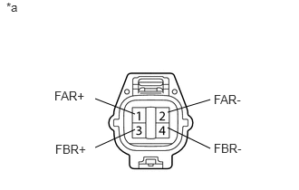
Measure the resistance according to the value(s) in the table below.
- Standard Resistance:
Tester Connection Condition Specified Condition 1 (FAR+) - 2 (FAR-) Always 6.4 to 7.2 Ω 3 (FBR+) - 4 (FBR-) Always 6.4 to 7.2 Ω
| *a | Component without harness connected
(Front Absorber Control Actuator RH) |
Check the front absorber control actuator LH (when DTC C1732 is output).
Disconnect the A57 actuator connector.
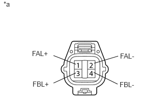
Measure the resistance according to the value(s) in the table below.
- Standard Resistance:
Tester Connection Condition Specified Condition 1 (FAL+) - 2 (FAL-) Always 6.4 to 7.2 Ω 3 (FBL+) - 4 (FBL-) Always 6.4 to 7.2 Ω
| *a | Component without harness connected
(Front Absorber Control Actuator LH) |
Check the rear absorber control actuator RH (when DTC C1733 is output).
Disconnect the S1 actuator connector.
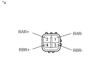
Measure the resistance according to the value(s) in the table below.
- Standard Resistance:
Tester Connection Condition Specified Condition 1 (RAR-) - 2 (RAR+) Always 6.4 to 7.2 Ω 3 (RBR-) - 4 (RBR+) Always 6.4 to 7.2 Ω
| *a | Component without harness connected
(Rear Absorber Control Actuator RH) |
Check the rear absorber control actuator LH (when DTC C1734 is output).
Disconnect the S4 actuator connector.
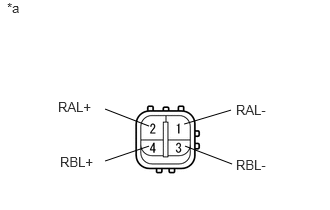
Measure the resistance according to the value(s) in the table below.
- Standard Resistance:
Tester Connection Condition Specified Condition 1 (RAL-) - 2 (RAL+) Always 6.4 to 7.2 Ω 3 (RBL-) - 4 (RBL+) Always 6.4 to 7.2 Ω
| *a | Component without harness connected
(Rear Absorber Control Actuator LH) |
| Result | Proceed to |
|---|---|
| OK | A |
| NG (Front absorber control actuator RH) | B |
| NG (Front absorber control actuator LH) | C |
| NG (Rear absorber control actuator RH) | D |
| NG (Rear absorber control actuator LH) | E |
A
B
C
D
E
Check the front side absorber control actuator.
Disconnect the A56 and/or A57 front absorber control actuator connector.
Disconnect the A14 suspension control ECU connector.
Measure the resistance according to the value(s) in the table below.
- Standard Resistance:
for Front RH (for DTC C1731) Tester Connection Condition Specified Condition A56-1 (FAR+) - A14-7 (FAR+) Always Below 1 Ω A56-2 (FAR-) - A14-8 (FAR-) Always Below 1 Ω A56-3 (FBR+) - A14-1 (FBR+) Always Below 1 Ω A56-4 (FBR-) - A14-2 (FBR-) Always Below 1 Ω A56-1 (FAR+) - Body ground Always 10 kΩ or higher A56-2 (FAR-) - Body ground Always 10 kΩ or higher A56-3 (FBR+) - Body ground Always 10 kΩ or higher A56-4 (FBR-) - Body ground Always 10 kΩ or higher
for Front LH (for DTC C1732) Tester Connection Condition Specified Condition A57-1 (FAL+) - A14-3 (FAL+) Always Below 1 Ω A57-2 (FAL-) - A14-5 (FAL-) Always Below 1 Ω A57-3 (FBL+) - A14-6 (FBL+) Always Below 1 Ω A57-4 (FBL-) - A14-4 (FBL-) Always Below 1 Ω A57-1 (FAL+) - Body ground Always 10 kΩ or higher A57-2 (FAL-) - Body ground Always 10 kΩ or higher A57-3 (FBL+) - Body ground Always 10 kΩ or higher A57-4 (FBL-) - Body ground Always 10 kΩ or higher
Check the rear side absorber control actuator.
Disconnect the S1 and/or S4 rear absorber control actuator connector.
Disconnect the R19 suspension control ECU connector.
Measure the resistance according to the value(s) in the table below.
- Standard Resistance:
for Rear RH (for DTC C1733) Tester Connection Condition Specified Condition S1-1 (RAR-) - R19-2 (RAR-) Always Below 1 Ω S1-2 (RAR+) - R19-1 (RAR+) Always Below 1 Ω S1-3 (RBR-) - R19-4 (RBR-) Always Below 1 Ω S1-4 (RBR+) - R19-3 (RBR+) Always Below 1 Ω S1-1 (RAR-) - Body ground Always 10 kΩ or higher S1-2 (RAR+) - Body ground Always 10 kΩ or higher S1-3 (RBR-) - Body ground Always 10 kΩ or higher S1-4 (RBR+) - Body ground Always 10 kΩ or higher
for Rear LH (for DTC C1734) Tester Connection Condition Specified Condition S4-1 (RAL-) - R19-6 (RAL-) Always Below 1 Ω S4-2 (RAL+) - R19-5 (RAL+) Always Below 1 Ω S4-3 (RBL-) - R19-8 (RBL-) Always Below 1 Ω S4-4 (RBL+) - R19-7 (RBL+) Always Below 1 Ω S4-1 (RAL-) - Body ground Always 10 kΩ or higher S4-2 (RAL+) - Body ground Always 10 kΩ or higher S4-3 (RBL-) - Body ground Always 10 kΩ or higher S4-4 (RBL+) - Body ground Always 10 kΩ or higher
OK
NG