AC60F AUTOMATIC TRANSMISSION / TRANSAXLE AUTOMATIC TRANSMISSION ASSEMBLY(for 1GD-FTV) REMOVAL
CAUTION / NOTICE / HINT
The necessary procedures (adjustment, calibration, initialization, or registration) that must be performed after parts are removed, installed, or replaced during the automatic transmission assembly removal/installation are shown below.
| Replacement Part or Procedure | Necessary Procedures | Effects/Inoperative when not Performed | Link |
|---|---|---|---|
| Battery terminal is disconnected/reconnected | Correction of steering angle neutral point | Multi-terrain monitor system | ( ) |
for 1GD-FTV, w/ DPF:
Exhaust manifold converter sub-assembly |
Clear DPF deterioration data | - | ()
|
for 1GD-FTV, w/ Urea SCR System:
Exhaust manifold converter sub-assembly |
Clear DPF deterioration data | - | ()
|
Starter assembly
|
Clear the number of starter operations | Stop and start system | ()
|
| Automatic transmission assembly | Reset memory | ·
Large shift shock ·
Engine overruns |
()
|
| Automatic transmission fluid | ATF thermal degradation estimate reset | The value of the Data List item "ATF Thermal Degradation Estimate" is not estimated correctly. |
- HINT:
-
When the cable is disconnected / reconnected to the battery terminal, systems temporarily stop operating. However, each system has a function that completes learning the first time the system is used.
-
Learning completes when vehicle is driven
Effect/Inoperative Function When Necessary Procedures are not Performed Necessary Procedures Link Lane departure alert system Drive the vehicle straight ahead at 40 km/h (25 mph) or more for 10 seconds or more. ( )
Pre-collision system Lighting system (EXT) (for LED Headlight) Stop and start system Drive the vehicle until stop and start control is permitted (approximately 5 to 60 minutes) ( )
Vehicle stability control system (for Hydraulic brake booster) Drive the vehicle straight ahead at 40 km/h (25 mph) or more for at least 10 seconds. ( )
- CAUTION:
- ·
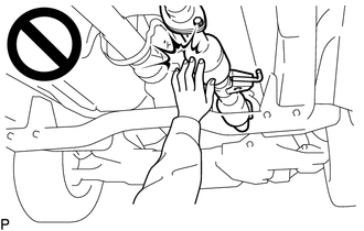
To prevent burns, do not touch the engine, exhaust pipe or other high temperature components while the engine is hot.
·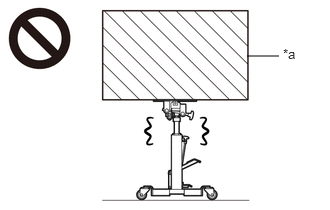 2.573,0.583 2.906,0.583 false 2.948,0.479 3.26,0.677 0.313,0.198 10 false *a
*a Object Exceeding Weight Limit of Transmission Jack
The automatic transmission assembly is very heavy. Be sure to follow the procedure described in the repair manual, or the transmission jack may suddenly drop or a part may fall.
PROCEDURE

 1. PRECAUTION
- NOTICE:
-
After turning the ignition switch is turned off, there may be a waiting time before disconnecting the negative (-) battery terminal.
-
(See page General>INTRODUCTION>REPAIR INSTRUCTION>PRECAUTION)
2.DISCONNECT CABLE FROM NEGATIVE BATTERY TERMINAL
51405A
3.REMOVE NO. 1 ENGINE UNDER COVER SUB-ASSEMBLY
51450
4.REMOVE REAR ENGINE UNDER COVER ASSEMBLY
5.DRAIN AUTOMATIC TRANSMISSION FLUID
6.DRAIN TRANSFER OIL
37110
7.REMOVE PROPELLER SHAFT ASSEMBLY
37140
8.REMOVE FRONT PROPELLER SHAFT ASSEMBLY
17410
9.REMOVE FRONT EXHAUST PIPE ASSEMBLY
28100
10.DISCONNECT STARTER ASSEMBLY
for 2.0 kW Type:
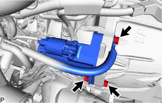
Remove the 2 bolts and nut and disconnect the starter assembly.
- HINT:
-
Tie the starter assembly with a string.
for 2.7 kW Type:
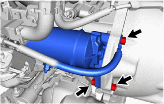
Remove the bolt and 2 nuts and disconnect the starter assembly.
- HINT:
-
Tie the starter assembly with a string.
12156
11.REMOVE OIL PAN INSULATOR
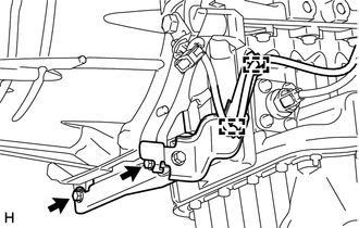
Disconnect the 2 wire harness clamps.
Remove the 2 bolts and oil pan insulator.
32101A
12.REMOVE DRIVE PLATE AND TORQUE CONVERTER ASSEMBLY SETTING BOLT
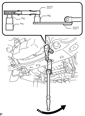
| *a | Socket Adaptor (Square drive 12.7 to 9.5 mm)
(Tool No. 09022-3C110) |
| *b | Socket Adaptor (Square drive 9.5 mm to 12.7 mm)
(Tool No. 09022-3C100) |
| *c | 17 mm Socket Wrench
(Tool No. 09011-2C500) |

|
Turn |
Using SST, turn the crankshaft to gain access to the locations of the 6 drive plate and torque converter assembly setting bolts and remove each bolt while holding the crankshaft pulley bolt with a wrench.
- HINT:
-
There will be one black colored bolt.
- SST
- 09961-01270
09970-10010 (09970-00010)
33820B
13.DISCONNECT TRANSMISSION CONTROL CABLE ASSEMBLY
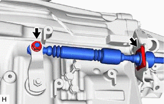
Remove the clip and nut and disconnect the transmission control cable assembly from the transmission control shaft lever LH and transmission control cable bracket.
35979B
14.REMOVE TRANSMISSION INSULATOR RH
15.DISCONNECT OIL COOLER TUBE
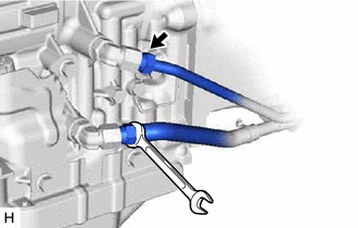
Disconnect the 2 oil cooler tubes from the automatic transmission assembly.
- HINT:
-
Use a container to catch any ATF.
Remove the bolt and flexible hose clamp.
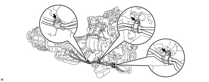
| *1 | Flexible Hose Clamp | - | - |
Remove the 2 bolts and disconnect the 2 oil cooler tubes from the automatic transmission assembly.
51225B
16.REMOVE FRONT SUSPENSION MEMBER BRACKET LH AND RH
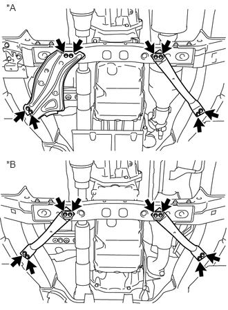
Remove the 8 bolts, front suspension member bracket LH and RH from the No. 3 frame crossmember sub-assembly and vehicle body.
| *A | w/ Urea SCR System |
| *A | w/o Urea SCR System |
35000
17.SUPPORT AUTOMATIC TRANSMISSION ASSEMBLY
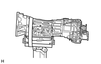
Support the automatic transmission assembly with a transmission jack.
- NOTICE:
- ·
In order to protect the automatic transmission oil pan sub-assembly, place attachments on the transmission jack.
·Make sure that the attachments and the automatic transmission oil pan sub-assembly are centered on the transmission jack.
·To prevent the automatic transmission oil pan sub-assembly from deforming, do not place any attachments under the automatic transmission oil pan sub-assembly of the automatic transmission assembly.
·Secure the automatic transmission assembly to the transmission jack using a belt, etc. to prevent it from falling.
77801A
18.DISCONNECT UREA TANK SUB-ASSEMBLY
51203
19.REMOVE NO. 3 FRAME CROSSMEMBER SUB-ASSEMBLY
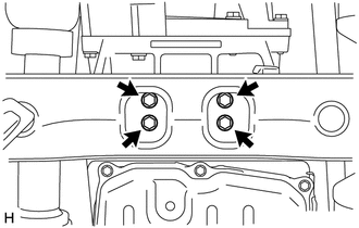
Remove the 4 bolts and disconnect the No. 3 frame crossmember sub-assembly from the rear No. 1 engine mounting insulator.
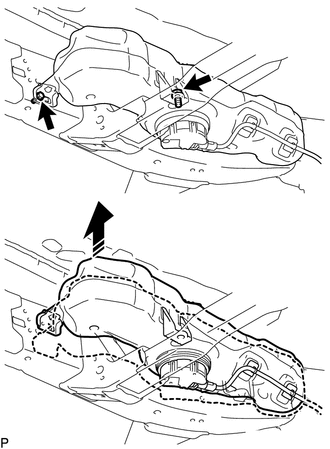
w/ Urea SCR System:
Remove the 2 bolts as shown in the illustration, raise the urea tank sub-assembly and hold it in position.
- HINT:
-
Only raise the urea tank enough to remove the fixing bolts on the No. 3 frame crossmember sub-assembly. Do not raise it any higher.
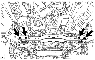
Remove the 4 bolts, 4 nuts and No. 3 frame crossmember sub-assembly from the vehicle body.
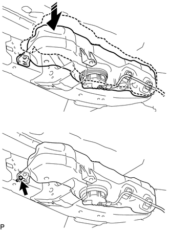
w/ Urea SCR System:
Temporarily install the urea tank sub-assembly with the bolt as shown in the illustration.
12371
20.REMOVE REAR NO. 1 ENGINE MOUNTING INSULATOR
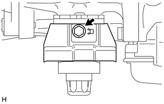
w/ Heat Insulator:
Remove the bolt and engine mounting heat insulator from the rear No. 1 engine mounting insulator.
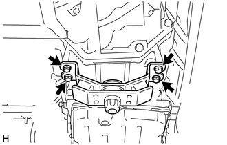
Remove the 4 bolts and rear No. 1 engine mounting insulator from the automatic transmission assembly.
21.DISCONNECT WIRE HARNESS
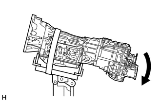
Tilt down the automatic transmission assembly.
- NOTICE:
-
Make sure that the cooling fan and fan shroud do not contact the engine assembly when tilting the automatic transmission assembly.
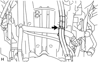
Disconnect the breather hose from the wire harness.
Disconnect the park/neutral position switch connector, transmission wire connector, 2 speed sensor connectors and transfer connector.
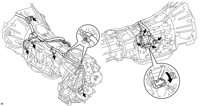
- HINT:
-
Detach the claw, press down the lever, and then disconnect the transmission wire connector.
Detach the 2 wire harness clamps.
Remove the 4 bolts and disconnect the wire harness from the automatic transmission assembly.
35000
22.REMOVE AUTOMATIC TRANSMISSION ASSEMBLY
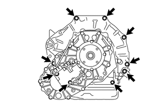
Remove the 9 bolts and automatic transmission assembly from the engine assembly.
- NOTICE:
-
To prevent damage to the 2 knock pins, do not pry between the automatic transmission assembly and engine assembly.
36478A
23.REMOVE TRANSMISSION BREATHER BRACKET
- HINT:
-
It is not necessary to remove the transmission breather bracket unless it is being replaced.
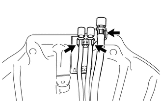
Disconnect the 3 breather hoses from the transmission breather bracket.
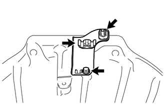
Remove the bolt and transmission breather bracket from the automatic transmission assembly.
Remove the 2 clamps from the transmission breather bracket.
36100
24.REMOVE TRANSFER ASSEMBLY
33823
25.REMOVE TRANSMISSION CONTROL CABLE BRACKET
- HINT:
-
It is not necessary to remove the transmission control cable bracket unless it is being replaced.
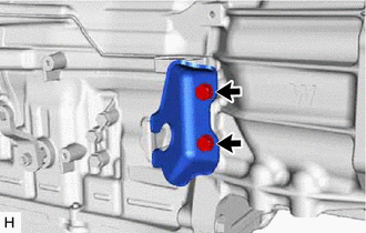
Remove the 2 bolts and transmission control cable bracket from the automatic transmission assembly.
3516A
26.REMOVE TRANSMISSION OIL PAN HEAT INSULATOR
- HINT:
-
It is not necessary to remove the transmission oil pan heat insulator unless it is being replaced.
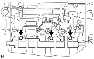
Remove the 3 bolts and transmission oil pan heat insulator from the automatic transmission assembly.
27.REMOVE TORQUE CONVERTER ASSEMBLY
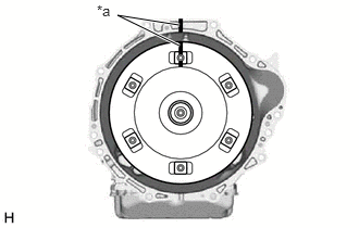
Put matchmarks on the automatic transmission assembly and the torque converter assembly.
| *a | Matchmark |
Remove the torque converter assembly from the automatic transmission assembly.
- NOTICE:
-
Remove the torque converter assembly from the input shaft horizontally.
28.REMOVE WIRE HARNESS CLAMP BRACKET
- HINT:
-
It is not necessary to remove the wire harness clamp brackets unless they are being replaced.
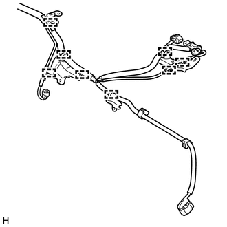
Detach the 8 wire harness clamps and 4 wire harness clamp brackets from the wire harness.
29.INSPECT TORQUE CONVERTER ASSEMBLY
32111
30.INSPECT PUMP IMPELLER DRIVE PLATE