1GD-FTV FUEL FUEL INJECTOR INSTALLATION
CAUTION / NOTICE / HINT
- NOTICE:
- ·
When replacing the parts in the following chart (A), replace the No. 1 injection pipe subassembly, No. 2 injection pipe sub-assembly and/or fuel inlet pipe sub-assembly with new ones.
Replaced Parts (A) Pipes Requiring New Replacement Injector assembly (including shuffling the injector assemblies between the cylinders) ·No. 1 injection pipe sub-assembly
·No. 2 injection pipe sub-assembly
Supply pump assembly Fuel inlet pipe sub-assembly ·Common rail assembly
·Cylinder block sub-assembly
·Cylinder head sub-assembly
·Cylinder head gasket
·Timing chain case assembly
·No. 1 injection pipe sub-assembly
·No. 2 injection pipe sub-assembly
·Fuel inlet pipe sub-assembly
·After removing the No. 1 injection pipe sub-assembly, No. 2 injection pipe sub-assembly and/or fuel inlet pipe sub-assembly, clean them with a brush and compressed air.
·The injector assembly is a precision instrument. Do not use the injector assembly if it is struck or dropped.
·Make sure foreign matter does not enter the fuel path.
PROCEDURE

 23682
1.INSTALL NOZZLE HOLDER GASKET
Install 4 new nozzle holder gaskets to the cylinder head cover sub-assembly.
23670
2.TEMPORARILY INSTALL INJECTOR ASSEMBLY
- HINT:
-
Before installing the injector assembly, check for carbon, foreign matter, etc. on the seal surfaces of the cylinder head sub-assembly and injector assembly. If there is foreign matter, remove it before installing the injector assembly.
Install 4 new injection nozzle seats to the cylinder head sub-assembly.
Apply a light coat of engine oil to the O-ring on each injector assembly.
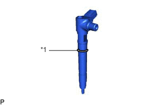
| *1 | O-Ring |
Install a new O-ring to each injector assembly.
| *1 | O-Ring |
Install the 4 injector assemblies to the cylinder head sub-assembly.
- NOTICE:
-
Fit the injector assembly to the injection nozzle seats.
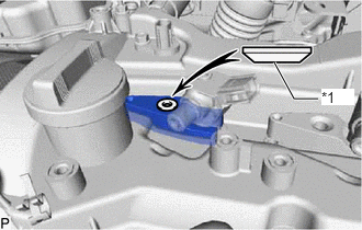
| *1 | Washer |
Install the nozzle holder clamps and washers as shown in the illustration.
- NOTICE:
-
Pay attention to the mounting orientation (beveled edge) of the washer.
Temporarily install the nozzle holder clamp bolts.
- NOTICE:
-
When temporarily installing the nozzle holder clamp bolt to the No. 1 nozzle holder clamp, make sure that the bolt and clamp are not at an angle.
- HINT:
-
Apply a light coat of engine oil to the threads of the nozzle holder clamp bolts.
3.TEMPORARILY INSTALL NO. 1 AND NO. 2 INJECTION PIPE SUB-ASSEMBLY
Temporarily install the 2 No. 2 injection pipe sub-assemblies 4 union nuts.
Temporarily install the 2 No. 1 injection pipe sub-assemblies 4 union nuts.
23670
4.TIGHTEN INJECTOR ASSEMBLY
Tighten the 4 nozzle holder clamp bolts.
- Torque:
- 21 N*m (214 kgf*cm, 15 ft.*lbf)
5.TIGHTEN NO. 1 AND NO. 2 INJECTION PIPE SUB-ASSEMBLY
With Common Rail Side Number Mark (24N):
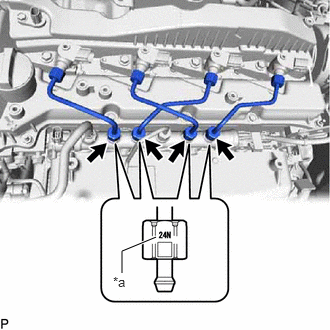
| *a | Number Mark (24N) |
Make sure that the "24N" mark faces the common rail side of the injection pipe at the position shown in the illustration.
- NOTICE:
-
Check for the number mark and tighten the parts to the specified tightening torque.
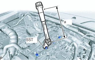
| *a | Torque Wrench Fulcrum Length |
Using SST, tighten the No. 1 and No. 2 injection pipe sub-assemblies 8 union nuts.
- SST
- 09245-11010
- Torque:
- Specified tightening torque : 24 N*m (245 kgf*cm, 18 ft.*lbf)
- HINT:
- ·
Calculate the torque wrench reading when changing the fulcrum length of the torque wrench.
Click hereGeneral>INTRODUCTION>REPAIR INSTRUCTION>PRECAUTION
·When using SST (fulcrum length of 50 mm (1.97 in.)) + torque wrench (fulcrum length of 180 mm (7.09 in.)): 18.8 N*m (192 kgf*cm, 14 ft.*lbf)
| *a | Torque Wrench Fulcrum Length |
Without Common Rail Side Number Mark (24N):
Using SST, tighten the No. 1 and No. 2 injection pipe sub-assemblies 8 union nuts.
- SST
- 09245-11010
- Torque:
- Specified tightening torque : 40 N*m (408 kgf*cm, 30 ft.*lbf)
- HINT:
- ·
Calculate the torque wrench reading when changing the fulcrum length of the torque wrench.
Click hereGeneral>INTRODUCTION>REPAIR INSTRUCTION>PRECAUTION
·When using SST (fulcrum length of 50 mm (1.97 in.)) + torque wrench (fulcrum length of 180 mm (7.09 in.)): 31 N*m (316 kgf*cm, 23 ft.*lbf)
23760
6.INSTALL NOZZLE LEAKAGE PIPE ASSEMBLY
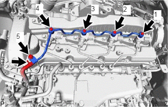
Temporarily install the nozzle leakage pipe assembly and 4 new gaskets with the 4 union bolts and bolt.
Tighten the 4 union bolts and bolt in the order shown in the illustration.
- Torque:
- 10 N*m (102 kgf*cm, 7 ft.*lbf)
Connect the No. 5 fuel hose to the nozzle leakage pipe assembly.
7.INSTALL HARNESS BRACKET
Install the harness bracket with the bolt.
- Torque:
- 8.4 N*m (86 kgf*cm, 74 in.*lbf)
8.INSTALL WIRING HARNESS CLAMP BRACKET
Install the wiring harness clamp bracket with bolt to the cylinder head cover sub-assembly.
- Torque:
- 10 N*m (102 kgf*cm, 7 ft.*lbf)
Connect the pressure discharge valve connector to the common rail assembly.
23811H
9.INSTALL NO. 1 FUEL PIPE (w/ DPF)
89463C
10.CONNECT NO. 1 NITROGEN OXIDES SENSOR (w/ Urea SCR System)
Connect the No. 1 nitrogen oxides sensor with the 2 bolts to the cylinder head cover sub-assembly.
- Torque:
- 13 N*m (133 kgf*cm, 10 ft.*lbf)
Connect the No. 1 nitrogen oxides sensor connector.
25624
11.INSTALL EGR VALVE ADAPTER (w/o EGR System)
82121
12.CONNECT ENGINE WIRE (w/o EGR System)
44306
13.CONNECT VANE PUMP OIL RESERVOIR SUB-ASSEMBLY (w/o EGR System)
12632
14.INSTALL NO. 2 ENGINE COVER BRACKET (w/o EGR System)
12633
15.INSTALL NO. 3 ENGINE COVER BRACKET (w/o EGR System)
16278
16.INSTALL NO. 2 WATER BY-PASS PIPE (w/o EGR System)
87209
17.INSTALL WATER HOSE SUB-ASSEMBLY (w/o EGR System)
26100G
18.INSTALL DIESEL THROTTLE BODY ASSEMBLY (w/o EGR System)
55781E
19.INSTALL COWL TOP VENTILATOR LOUVER SUB-ASSEMBLY (w/o EGR System)
25800
20.INSTALL ELECTRIC EGR CONTROL VALVE ASSEMBLY (w/ EGR System without EGR Cooler)
25800
21.INSTALL EGR COOLER ASSEMBLY (w/ EGR System with EGR Cooler)
22.CONNECT CABLE TO NEGATIVE BATTERY TERMINAL
23. INITIALIZATION AFTER RECONNECTING BATTERY TERMINAL
Click hereGeneral>SETUP>WHEN DISCONNECTING OR RECONNECTING BATTERY TERMINAL>WORK PROCEDURE
- HINT:
-
When disconnecting and reconnecting the battery, there is an automatic learning function that completes learning when the respective system is used.
-
Click hereGeneral>SETUP>WHEN DISCONNECTING OR RECONNECTING BATTERY TERMINAL>AUTOMATIC LEARNING CHART
24.ADD ENGINE COOLANT (w/o EGR System)
25.INSPECT FOR COOLANT LEAK (w/o EGR System)
26.BLEED AIR FROM FUEL SYSTEM
27.INSPECT FOR FUEL LEAK