STEERING COLUMN STEERING COLUMN ASSEMBLY(for Manual Tilt and Manual Telescopic Steering Column) REMOVAL
CAUTION / NOTICE / HINT
- CAUTION:
-
Some of these service operations affect the SRS airbag system. Read the precautionary notices concerning the SRS airbag system before servicing the steering wheel (See page Vehicle Interior>SUPPLEMENTAL RESTRAINT SYSTEMS>AIRBAG SYSTEM>PRECAUTION).
- HINT:
- ·
Use the same procedure for RHD and LHD vehicles.
·The procedure listed below is for LHD vehicles.
PROCEDURE

 1. PRECAUTION
- CAUTION:
-
Wait at least 90 seconds after disconnecting the cable from the negative (-) battery terminal to disable the SRS system.
- NOTICE:
-
After turning the ignition switch off, waiting time may be required before disconnecting the cable from the negative (-) battery terminal.
-
Click hereGeneral>INTRODUCTION>REPAIR INSTRUCTION>PRECAUTION
2.DISCONNECT CABLE FROM NEGATIVE BATTERY TERMINAL
3.PLACE FRONT WHEELS FACING STRAIGHT AHEAD
4.REMOVE FRONT WHEEL LH
45100
5.REMOVE STEERING WHEEL ASSEMBLY
45287
6.REMOVE STEERING COLUMN LOWER COVER
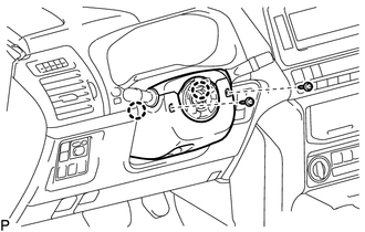
Remove the 2 screws.
Detach the 2 claws and remove the steering column lower cover.
45286B
7.REMOVE STEERING COLUMN UPPER COVER
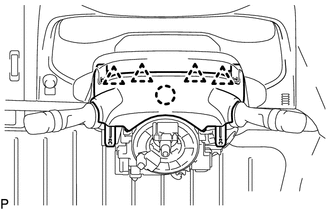
Detach the 4 clips.
Detach the claw and remove the steering column upper cover.
8.REMOVE COMBINATION SWITCH ASSEMBLY WITH SPIRAL CABLE SUB-ASSEMBLY
Disconnect the connectors from the combination switch with spiral cable.
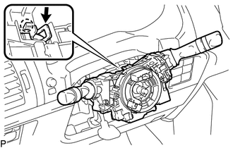
Use pliers to hold the clamp and raise the claw with a screwdriver. Then remove the combination switch assembly with spiral cable sub-assembly from the steering column assembly.
89783
9.REMOVE TRANSPONDER KEY AMPLIFIER (w/ Transponder Key)
55045
10.REMOVE INSTRUMENT LOWER PANEL FINISH PANEL SUB-ASSEMBLY (w/o Knee Airbag)
73900
11.REMOVE NO. 1 INSTRUMENT LOWER PANEL AIRBAG ASSEMBLY (w/ Knee Airbag)
45250
12.REMOVE STEERING COLUMN ASSEMBLY
Detach the claws and remove the wire harness protector and wire harness.
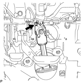
Put matchmarks on the steering intermediate shaft and steering column.
| *a | Matchmark |
Remove the bolt.
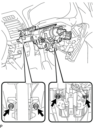
Remove the 4 nuts and steering column.
53737A
13.REMOVE NO. 1 FRONT FENDER APRON TO FRAME SEAL LH
45220
14.DISCONNECT STEERING INTERMEDIATE SHAFT ASSEMBLY
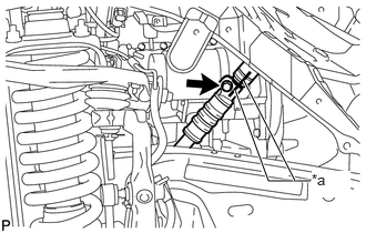
Put matchmarks on the steering intermediate shaft and No. 2 steering intermediate shaft.
| *a | Matchmark |
Remove the bolt, and then pull out the intermediate shaft toward the inside of the vehicle.
45025D
15.REMOVE NO. 1 STEERING COLUMN HOLE COVER SUB-ASSEMBLY
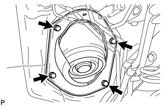
Remove the 4 bolts and steering column hole cover from the vehicle.
45203
16.DISCONNECT NO. 2 STEERING INTERMEDIATE SHAFT SUB-ASSEMBLY
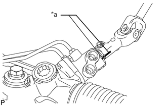
Put matchmarks on the No. 2 steering intermediate shaft and power steering gear.
| *a | Matchmark |
Remove the bolt and No. 2 steering intermediate shaft from the power steering gear.