1GD-FTV ENGINE CONTROL ECD SYSTEM(w/ DPF) Active Control Engine Mount System
DESCRIPTION
Refer to DTC P0A1412.
Click hereEngine / Hybrid System>1GD-FTV (ENGINE CONTROL)>ECD SYSTEM (w/ DPF)>P0A1412
WIRING DIAGRAM
Refer to DTC P0A1412.
Click hereEngine / Hybrid System>1GD-FTV (ENGINE CONTROL)>ECD SYSTEM (w/ DPF)>P0A1412
CAUTION / NOTICE / HINT
- NOTICE:
-
Inspect the fuses for circuits related to this system before performing the following procedure.
PROCEDURE
Connect the GTS to the DLC3.
Turn the engine switch on (IG) and turn the GTS on.
Enter the following menus: Powertrain / Engine / Trouble Codes.
Read the pending DTCs.
- Result:
Result Proceed to No DTC is output A DTC P0A1412 or P0A1414 is output B
A
B
Connect the GTS to the DLC3.
Turn the engine switch on (IG).
Turn the GTS on.
Enter the following menus: Powertrain / Engine / Active Test / Activate the ACM Inhibit.
According to the display on the GTS, perform the Active Test to operate the vacuum switching valve sub-assembly (for engine mounting) and for check the operating sound of the vacuum switching valve sub-assembly (for engine mounting).
- OK:
Operating sounds can be heard.
- Result:
Proceed to OK NG
OK
NG
Check the air and vacuum hoses for looseness, disconnection and blockage.
- OK:
No looseness, disconnection or blockage.
- Result:
Proceed to OK NG
OK
NG
Disconnect the vacuum hose from the vacuum pump assembly.
Start the engine.
Check that the disconnected port located on the vacuum pump assembly applies suction to your finger.
- OK:
Vacuum exists.
- Result:
Proceed to OK NG
OK
NG
Inspect the vacuum switching valve sub-assembly (for engine mounting).
- Result:
Proceed to OK NG
OK
NG
Click hereEngine / Hybrid System>1GD-FTV (ENGINE CONTROL)>VACUUM SWITCHING VALVE (for Engine Mounting)>REMOVAL
Disconnect the vacuum hose from the front engine mount insulator assembly.
Using a vacuum pump, apply vacuum of 80 kPa (600 mmHg, 23.622 in.Hg) and wait for 1 minute.
Check that there is no change in the needle movement of the vacuum pump gauge.
Check that there is no fluid leakage caused by a break in the diaphragm.
- OK:
Vacuum does not leak.
- Result:
Proceed to OK NG
Reconnect the vacuum hose.
OK
NG
Inspect the vacuum switching valve sub-assembly (for engine mounting).
- Result:
Proceed to OK NG
OK
NG
Click hereEngine / Hybrid System>1GD-FTV (ENGINE CONTROL)>VACUUM SWITCHING VALVE (for Engine Mounting)>REMOVAL
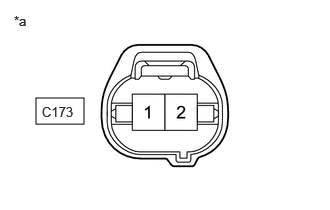
| *a | Front view of wire harness connector
(to Vacuum Switching Valve Sub-assembly (for Engine Mounting)) |
Disconnect the vacuum switching valve sub-assembly (for engine mounting) connector.
Turn the engine switch on (IG).
Measure the voltage according to the value(s) in the table below.
- Standard Voltage:
Tester Connection Condition Specified Condition C173-1 - Body ground Engine switch on (IG) 11 to 14 V
- Result:
Proceed to OK NG
OK
NG
Disconnect the vacuum switching valve sub-assembly (for engine mounting) connector.
Disconnect the ECM connector.
Measure the resistance according to the value(s) in the table below.
- Standard Resistance:
Tester Connection Condition Specified Condition C173-2 - G184-34 (ACM) Always Below 1 Ω C173-2 or G184-34 (ACM) - Body ground and other terminals Always 10 kΩ or higher
- Result:
Proceed to OK NG
OK
NG