1GD-FTV ENGINE CONTROL ECD SYSTEM Lack of Power (Turbocharger System)
CAUTION / NOTICE / HINT
- HINT:
- ·
The diagnosis flowchart is for lack of power due to turbocharger factors.
·If symptom-specific diagnosis indicates a turbocharger related problem, check using this flowchart.
PROCEDURE
Check that no soot or oil adheres to the turbocharger sub-assembly connectors.
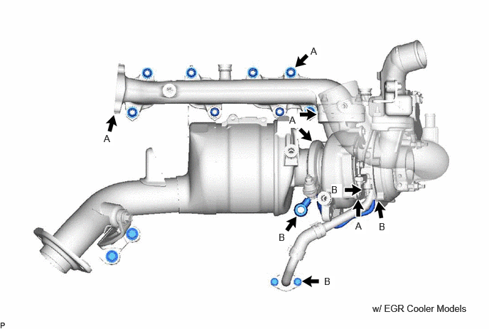
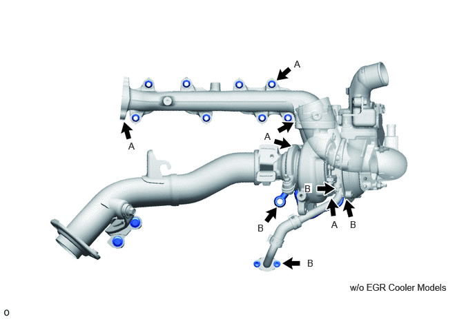
- HINT:
-
If adhering soot or an oil leak exists, air leaking at that position may be the cause of the lack of boost pressure.
- Result:
Result Proceed to No adhering soot or an oil A Soot adhering around the turbine housing, flange, or exhaust pipe clamp (A in the illustration)(w/ EGR Cooler) B Soot adhering around the turbine housing, flange, or exhaust pipe clamp (A in the illustration)(w/o EGR Cooler) C Oil leak from the contact surface between the compressor housing and bearing housing (B in the illustration) D
A
B
C
D
Click hereEngine / Hybrid System>1GD-FTV (INTAKE / EXHAUST)>EXHAUST MANIFOLD W/ TURBOCHARGER>REMOVAL
Check that the turbine shaft rotates smoothly, without catching.
Click hereEngine / Hybrid System>1GD-FTV (INTAKE / EXHAUST)>EXHAUST MANIFOLD W/ TURBOCHARGER>INSPECTION
Check for loose turbine mounting nuts and for axial play in the turbine shaft.
Click hereEngine / Hybrid System>1GD-FTV (INTAKE / EXHAUST)>EXHAUST MANIFOLD W/ TURBOCHARGER>INSPECTION
- HINT:
-
If the turbine shaft catches or if there no play or excessive play, it could indicate a seal problem due to seizing or poor sliding due to a deposit build up.
- Result:
Result Proceed to No turbine shaft malfunction A Turbine shaft malfunction B
A
B
Click hereEngine / Hybrid System>1GD-FTV (INTAKE / EXHAUST)>EXHAUST MANIFOLD W/ TURBOCHARGER>REMOVAL
Check for interference between the turbine wheel and the turbine housing.
Click hereEngine / Hybrid System>1GD-FTV (INTAKE / EXHAUST)>EXHAUST MANIFOLD W/ TURBOCHARGER>INSPECTION
- HINT:
-
When there is interference between the turbine wheel and turbine housing and the turbine wheel is damaged, check for fragments of the turbine wheel in the exhaust manifold converter sub-assembly.
- Result:
Result Proceed to No damage or interference A Damage or interference exists B
A
B
Click hereEngine / Hybrid System>1GD-FTV (INTAKE / EXHAUST)>EXHAUST MANIFOLD W/ TURBOCHARGER>REMOVAL
Inspect the turbocharger nozzle vane plate.
Remove the e-washer from the turbocharger nozzle vane control actuator.
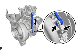
Move the turbocharger vane control rod sub-assembly and check that the turbocharger nozzle vane plate moves.
- Result:
Result Proceed to Catches, but operates* OK Gets stuck and does not operate NG
- HINT:
-
*: Check several times.
OK
Click hereEngine / Hybrid System>1GD-FTV (INTAKE / EXHAUST)>EXHAUST MANIFOLD W/ TURBOCHARGER>DISASSEMBLY
NG
Click hereEngine / Hybrid System>1GD-FTV (INTAKE / EXHAUST)>EXHAUST MANIFOLD W/ TURBOCHARGER>REMOVAL
Check for deformation or cracks in the mounting surfaces on the exhaust manifold converter sub-assembly and the turbocharger sub-assembly.
- HINT:
-
Deformation or cracks on a mounting surface may allow exhaust gas to leak from the damaged position.
- Standard:
No deformation or cracks on a mounting surface.
- Result:
Result Proceed to No problem with the mounting surface A Deformation or cracks on the exhaust manifold converter sub-assembly mounting surface B Deformation or cracks on the turbocharger sub-assembly mounting surface C
A
B
C
Click hereEngine / Hybrid System>1GD-FTV (INTAKE / EXHAUST)>EXHAUST MANIFOLD W/ TURBOCHARGER>REMOVAL
Replace the exhaust pipe clamp and the gasket.
- Result:
Proceed to NEXT
NEXT
Check that the abnormal state has disappeared.
- Result:
Proceed to NEXT
NEXT
Check for deformation or cracks in the mounting surfaces on the turbine outlet elbow and the turbocharger sub-assembly.
- HINT:
-
Deformation or cracks on a mounting surface may allow exhaust gas to leak from the damaged position.
- Standard:
No deformation or cracks on a mounting surface.
- Result:
Result Proceed to No problem with the mounting surface A Deformation or cracks on the turbine outlet elbow mounting surface B Deformation or cracks on the turbocharger sub-assembly mounting surface C
A
B
C
Click hereEngine / Hybrid System>1GD-FTV (INTAKE / EXHAUST)>EXHAUST MANIFOLD W/ TURBOCHARGER>REMOVAL
Replace the exhaust pipe clamp and the gasket.
- Result:
Proceed to NEXT
NEXT
Check that the abnormal state has disappeared.
- Result:
Proceed to NEXT
NEXT