BRAKE SYSTEM (OTHER) HYDRAULIC BRAKE BOOSTER(for RHD) INSTALLATION
PROCEDURE

 44785
1.INSTALL BRAKE BOOSTER GASKET
Install a new brake booster gasket to the hydraulic brake booster.
2.INSTALL HYDRAULIC BRAKE BOOSTER ASSEMBLY
Install the hydraulic brake booster assembly with the 4 nuts.
- Torque:
- 14 N*m (145 kgf*cm, 10 ft.*lbf)
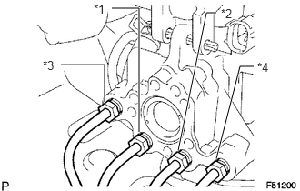
Connect the 4 brake lines to the correct positions of the hydraulic brake booster assembly as shown in the illustration.
- HINT:
- ·
*1: To front wheel cylinder RH
·*2: To front wheel cylinder LH
·*3: To rear wheel cylinder RH
·*4: To rear wheel cylinder LH
Install the clamp with the bolt.
- Torque:
- 8.5 N*m (87 kgf*cm, 75 in.*lbf)
Using a union nut wrench, connect the 4 brake lines to the hydraulic brake booster assembly.
- Torque:
- 15 N*m (155 kgf*cm, 11 ft.*lbf)
- NOTICE:
-
Use the formula to calculate special torque values for situations where a union nut wrench is combined with a torque wrench (See page General>INTRODUCTION>REPAIR INSTRUCTION>PRECAUTION).
Connect the 2 brake tube clamps to the body.
Install the brake tube to the clamps.
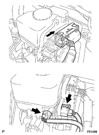
Connect the 3 connectors to the hydraulic brake booster.
47264A
3.INSTALL PUSH ROD PIN
31410
4.INSTALL CLUTCH MASTER CYLINDER ASSEMBLY
Install the clutch master cylinder assembly (See page Drivetrain>CLUTCH>CLUTCH MASTER CYLINDER (for RHD)>INSTALLATION).
5.CONNECT WATER HOSE JOINT
w/ Rear Heater:
Connect the water hose joint.
- Torque:
- 5.4 N*m (55 kgf*cm, 48 ft.*lbf)
73900
6.INSTALL LOWER NO . 1 INSTRUMENT PANEL AIRBAG ASSEMBLY
Install the lower No. 1 instrument panel airbag assembly (See page Vehicle Interior>SUPPLEMENTAL RESTRAINT SYSTEMS>KNEE AIRBAG ASSEMBLY>INSTALLATION).
7.CONNECT CABLE TO NEGATIVE BATTERY TERMINAL
8.BLEED BRAKE SYSTEM
9.FILL RESERVOIR WITH BRAKE FLUID
10.BLEED CLUTCH LINE
11.CHECK FLUID LEVEL IN RESERVOIR
12.CHECK FOR BRAKE FLUID LEAK FROM CLUTCH LINE
13.CHECK AND ADJUST BRAKE PEDAL
Check and adjust brake pedal (See page Brake>BRAKE SYSTEM (OTHER)>BRAKE PEDAL (for Hydraulic Brake Booster)>ADJUSTMENT).
47217
14.INSPECT BRAKE MASTER CYLINDER OPERATION
Inspect the brake master cylinder operation (See page Brake>BRAKE SYSTEM (OTHER)>HYDRAULIC BRAKE BOOSTER(for RHD)>ON-VEHICLE INSPECTION).
89180
15.PERFORM YAW RATE AND ACCELERATION SENSOR ZERO POINT CALIBRATION
- NOTICE:
-
When replacing the hydraulic brake booster assembly, perform yaw rate and acceleration sensor zero point calibration and acquire information about the following specification as necessary (See page Brake>BRAKE CONTROL / DYNAMIC CONTROL SYSTEMS>VEHICLE STABILITY CONTROL SYSTEM (for Hydraulic Brake Booster)>CALIBRATION),
- ·
Downhill assist control calibration
·Crawl control calibration
16. INITIALIZATION AFTER RECONNECTING BATTERY TERMINAL
Click hereGeneral>SETUP>WHEN DISCONNECTING OR RECONNECTING BATTERY TERMINAL>WORK PROCEDURE
- HINT:
-
When disconnecting and reconnecting the battery, there is an automatic learning function that completes learning when the respective system is used.
-
Click hereGeneral>SETUP>WHEN DISCONNECTING OR RECONNECTING BATTERY TERMINAL>AUTOMATIC LEARNING CHART