Cruise Main Indicator Light Circuit
Circuit diagnosis · Vehicles built from Jan 2012
DESCRIPTION
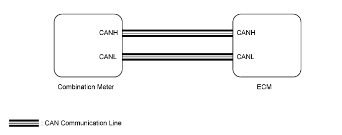
- The ECM detects a cruise control switch signal and sends it to the combination meter via the CAN communication line. Then the cruise control indicator light comes on.
- The cruise control indicator light circuit uses the CAN for communication. If there is a malfunction in this circuit, check for DTCs in the CAN communication system before troubleshooting this circuit.
WIRING DIAGRAM

INSPECTION PROCEDURE
| 1. PERFORM ACTIVE TEST USING INTELLIGENT TESTER (CRUISE CONTROL INDICATOR LIGHT) |

Using the intelligent tester, perform the Active Test (Click here).
Combination Meter Tester Display
Test Part
Control Range
Diagnostic Note
Indicat. Lamp Cruise
Cruise control indicator light operation
OFF or ON
-
- OK:
- Indicator light comes on/goes off.
|
|
||||

| OK | |
 |
| 2. READ VALUE USING INTELLIGENT TESTER (CRUISE CONTROL INDICATOR LIGHT) |
Using the intelligent tester, read the Data List (Click here).
Radar Cruise Tester Display
Measurement Item/Range
Normal Condition
Diagnostic Note
CCS Indicator M-CPU
Cruise control indicator light (Main CPU) / ON or OFF
ON: Cruise control indicator light on
OFF: Cruise control indicator light off
-
- OK:
- The intelligent tester display changes according to condition of cruise control indicator light.
| Result |
Proceed to |
| OK |
A |
| NG (for 1UR-FE) |
B |
| NG (for 3UR-FE) |
C |
|
|
||||
|
|
||||
| A | ||
 |
||
| ||