2011-2013 Land Cruiser · Service Manual Vehicle Interior

Security Indicator Light Circuit

Circuit diagnosis · Vehicles built Sep 2011 – Dec 2011

Versions by build date: Sep 2011 – Dec 2011 from Jan 2012

DESCRIPTION

  1. When the theft deterrent system is in the disarmed state, the security indicator will flash continuously if the immobiliser system is set, or not illuminate if the immobiliser system is not set.
    When the theft deterrent system is in the armed state, the immobiliser system is automatically set and the security indicator will flash continuously.
    When the theft deterrent system is in the arming preparation state and alarm sounding state, the certification ECU (smart key ECU assembly) causes the security indicator to be illuminated.

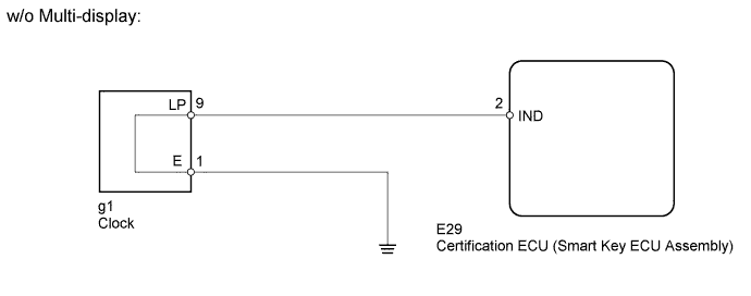
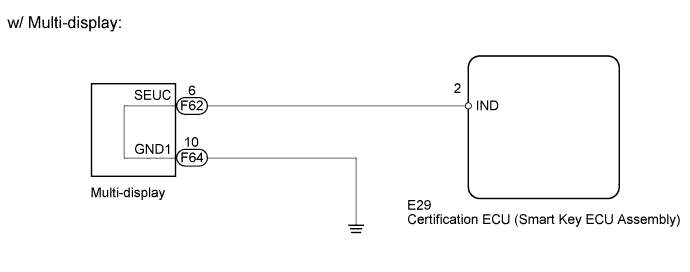
WIRING DIAGRAM

E197505E01
B184353E18

INSPECTION PROCEDURE


1. PERFORM ACTIVE TEST USING INTELLIGENT TESTER (SECURITY INDICATOR)
  1. Operate the intelligent tester according to the steps on the display and select "Active Test".
    Entry&Start 
    Tester Display
    Test Part
    Control Range
    Diagnostic Note
    Security Indicator
    Security indicator
    ON / OFF
    -

    OK:
    Security indicator illuminates.


NG
Go to step 2
OK

REPLACE CERTIFICATION ECU (SMART KEY ECU ASSEMBLY)

2. CHECK VEHICLE EQUIPMENT
  1. Check if the multi-display is equipped on the vehicle.

    Result 
    Result
    Proceed to
    w/ Multi-display
    A
    w/o Multi-display
    B


B
Go to step 4
A


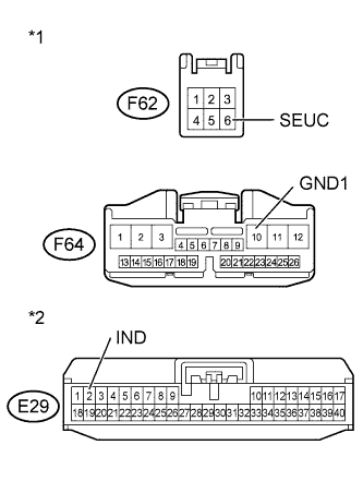
3. CHECK HARNESS AND CONNECTOR (MULTI-DISPLAY - CERTIFICATION ECU (SMART KEY ECU ASSEMBLY) AND BODY GROUND)
E197514E01
  1. Disconnect the F62 and F64 display connector.

  1. Disconnect the E29 ECU connector.

  1. Measure the resistance according to the value(s) in the table below.

    Standard Resistance:
    Tester Connection
    Condition
    Specified Condition
    F62-6 (SEUC) - E29-2 (IND)
    Always
    Below 1 Ω
    F64-10 (GND1) - Body ground
    Always
    Below 1 Ω
    F62-6 (SEUC) or E29-2 (IND) - Body ground
    Always
    10 kΩ or higher

Text in Illustration 
*1
Front view of wire harness connector
(to Multi-display)
*2
Front view of wire harness connector
(to Certification ECU (Smart Key ECU Assembly))


NG
REPAIR OR REPLACE HARNESS OR CONNECTOR
OK

REPLACE MULTI-DISPLAY (Click here)

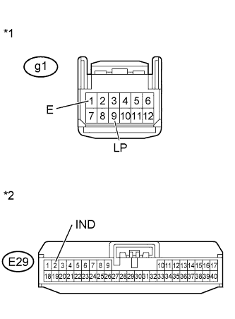
4. CHECK HARNESS AND CONNECTOR (CLOCK - CERTIFICATION ECU (SMART KEY ECU ASSEMBLY) AND BODY GROUND)
B184355E03
  1. Disconnect the g1 clock connector.

  1. Disconnect the E29 ECU connector.

  1. Measure the resistance according to the value(s) in the table below.

    Standard Resistance:
    Tester Connection
    Condition
    Specified Condition
    g1-9 (LP) - E29-2 (IND)
    Always
    Below 1 Ω
    g1-1 (E) - Body ground
    Always
    Below 1 Ω
    g1-9 (LP) or E29-2 (IND) - Body ground
    Always
    10 kΩ or higher

Text in Illustration 
*1
Front view of wire harness connector
(to Clock)
*2
Front view of wire harness connector
(to Certification ECU [Smart Key ECU Assembly])


NG
REPAIR OR REPLACE HARNESS OR CONNECTOR
OK

REPLACE CLOCK (Click here)


← Theft Warning Siren Circuit (from Jan 2012)Security Indicator Light Circuit (from Jan 2012) →