REMOVAL
Removal / installation · Vehicles built from Sep 2011
- HINT:
- Use the same procedures for the LH side and RH side.
- The procedures listed below are for the LH side.
- Use the same procedures for the LH side and RH side.
| 1. REMOVE REAR WHEEL |
| 2. DISCONNECT REAR DISC BRAKE CYLINDER ASSEMBLY LH |

Remove the 2 bolts and disconnect the rear disc brake cylinder.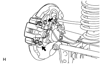

- NOTICE:
- Do not disconnect the flexible hose from the disc brake cylinder.
- Do not twist or bend the flexible hose.
- Do not disconnect the flexible hose from the disc brake cylinder.
Hang the disc brake cylinder with a piece of wire.
| 3. REMOVE REAR DISC |
Put matchmarks on the rear disc and axle hub if planning to reuse the disc.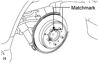
Turn the shoe adjuster as shown in the illustration until the disc turns freely, and then remove the disc.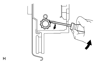
| 4. REMOVE PARKING BRAKE SHOE RETURN SPRING |
Using SST, remove the return spring.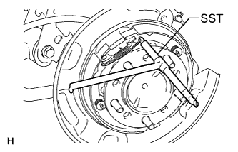
- SST
- 09703-30011
| 5. REMOVE NO. 1 PARKING BRAKE SHOE ASSEMBLY LH |
Using SST, remove the shoe hold down spring cup, compression spring and shoe hold down spring pin.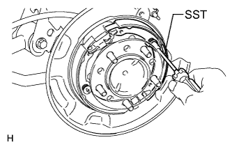
- SST
- 09718-00011
Disconnect the tension spring from the No. 1 parking brake shoe.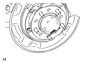
Remove the No. 1 parking brake shoe and shoe adjuster screw set.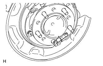
| 6. REMOVE NO. 2 PARKING BRAKE SHOE ASSEMBLY LH |
Using SST, remove the shoe hold down spring cup, compression spring and shoe hold down spring pin.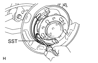
- SST
- 09718-00011
Remove the No. 2 parking brake shoe.
| 7. REMOVE PARKING BRAKE SHOE LEVER LH |
Disconnect the No. 3 parking brake cable from the parking brake shoe lever.
Remove the parking brake shoe lever.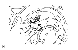
| 8. DISCONNECT NO. 3 PARKING BRAKE CABLE ASSEMBLY |
Remove the bolt and No. 3 parking brake cable.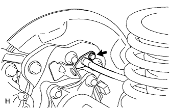
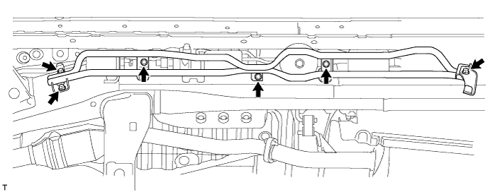
| 9. REMOVE HEIGHT CONTROL UNIT PROTECTOR PIPE |
Remove the 6 bolts and protector pipe.
| 10. REMOVE REAR NO. 2 SUSPENSION CONTROL ACCUMULATOR BRACKET |
Remove the bolt and bracket from the shock absorber control valve.
| 11. REMOVE LOWER CONSOLE BOX (w/o Console Box Lid) |
| 12. REMOVE COOLING BOX ASSEMBLY (w/ Cool Box) |
| 13. REMOVE REAR CONSOLE BOX SUB-ASSEMBLY (w/o Cool Box) |
| 14. REMOVE NO. 2 PARKING BRAKE CABLE ASSEMBLY |
Loosen the adjusting nut.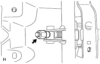
Disconnect the No. 2 parking brake cable from the No. 1 parking brake pull rod.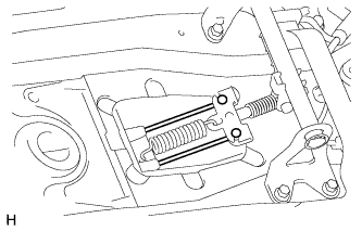
Pinch the claws of the No. 2 parking brake cable and push the cable outside of the vehicle slightly.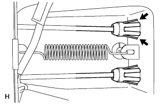
Tilt the fuel tank (Click here) so that bolt A in the illustration can be removed.
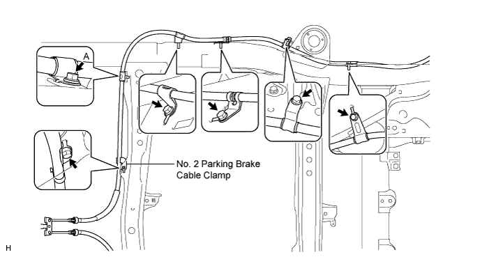
Remove the 6 bolts and No. 2 parking brake cable.
Remove the No. 2 parking brake cable clamp from the No. 2 parking brake cable.
| 15. REMOVE NO. 3 PARKING BRAKE CABLE ASSEMBLY |
Loosen the adjusting nut.
Disconnect the No. 3 parking brake cable from the No. 1 parking brake pull rod.
Pinch the claws of the No. 3 parking brake cable and push the cable outside of the vehicle slightly.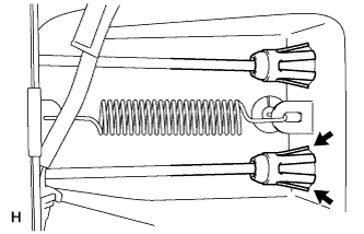
Remove the 6 bolts and No. 3 parking brake cable.
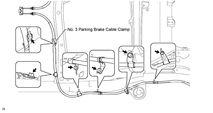
Remove the No. 3 parking brake cable clamp from the No. 3 parking brake cable.