P0418 Secondary Air Injection System Control "A" Circuit
Diagnostic trouble codes · Vehicles built Sep 2011 – Dec 2011
DESCRIPTION
The diagnostic trouble code (DTC) indicates an open or short in the air pump circuit of the secondary air injection (AIR) system. The air injection control driver diagnoses the air pump circuit, E-ASV circuit and itself, and sends the diagnosis signal to the engine control module (ECM). If the ECM receives a malfunction signal from the air injection control driver, the ECM illuminates the malfunction indicator lamp (MIL), and stores a DTC.The secondary air injection (AIR) system introduces fresh air into the exhaust manifold in order to reduce carbon monoxide (CO) and hydrocarbon (HC) in the exhaust emission. This system is activated just after the engine start, and is stopped when the catalyst converter is warmed-up. This system consists of the following components: 1) the air pump which sends fresh air to the exhaust manifold, 2) the electric air switching valve (E-ASV) which switches the fresh air flow, 3) the air switching valve (ASV) which switches the air passage to the exhaust manifold of each bank, 4) the vacuum switching valve (VSV) which switches the vacuum (intake manifold pressure) to operate the ASV, 5) the pressure sensor which detects the fresh air pressure and exhaust pulse, 6) the air injection control driver which controls the power sources of the air pump and E-ASV, 7) the engine control module (ECM) which controls and monitors this system.
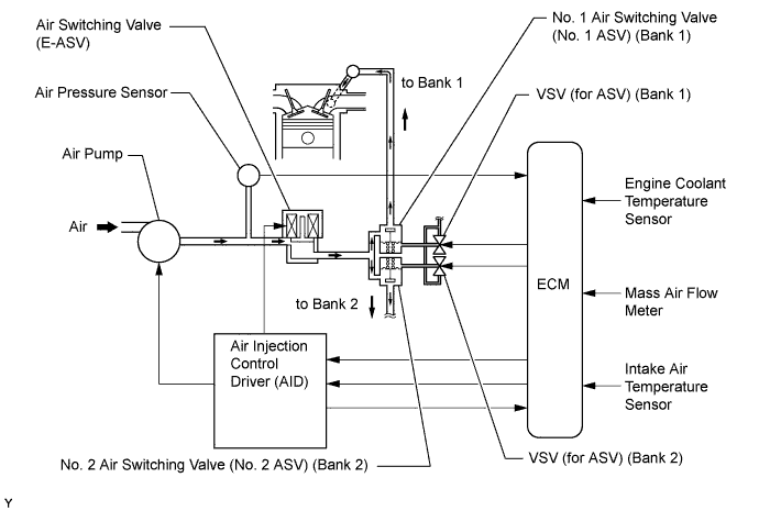

| DTC Code |
DTC Detection Condition |
Trouble Area |
| P0418 |
The ECM receives a diagnostic signal from the driver (20% duty-cycle) (1 trip detection logic). |
|
WIRING DIAGRAM
Refer to DTC P0412 (Click here).INSPECTION PROCEDURE
- HINT:
- Read freeze frame data using the intelligent tester. Freeze frame data records the engine conditions when malfunctions are detected. When troubleshooting, freeze frame data can help determine if the vehicle was running or stopped, if the engine was warmed up or not, if the air -fuel ratio was lean or rich, and other data from the time the malfunction occurred.
| 1. CHECK HARNESS AND CONNECTOR (AIR INJECTION CONTROL DRIVER - BODY GROUND) |

Disconnect the air injection control driver connector.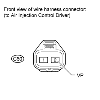
Measure the resistance according to the value(s) in the table below.
- Standard Resistance:
Tester Connection
Condition
Specified Condition
C60-2 (VP) - Body ground
Always
0.4 to 1.0 Ω
|
|
||||

| OK | ||
 |
||
| ||
| 2. INSPECT AIR PUMP |
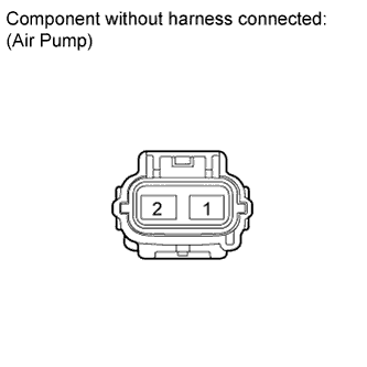 |
Remove the intake manifold (Click here).
Disconnect the air pump connector.
Measure the resistance according to the value(s) in the table below.
- Standard Resistance:
Tester Connection
Condition
Specified Condition
1 - 2
Always
0.4 to 1.0 Ω
|
|
||||

| OK | |
 |
| 3. CHECK HARNESS AND CONNECTOR (AIR PUMP - BODY GROUND) |
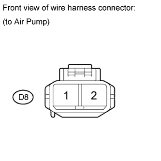 |
Remove the intake manifold (Click here).
Disconnect the air pump connector.
Measure the resistance according to the value(s) in the table below.
- Standard Resistance:
Tester Connection
Condition
Specified Condition
D8-1 - Body ground
Always
Below 1 Ω
|
|
||||
| OK | |
|
| 4. CHECK HARNESS AND CONNECTOR (AIR INJECTION CONTROL DRIVER - AIR PUMP) |
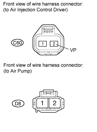 |
Remove the intake manifold (Click here).
Disconnect the air injection control driver connector.
Disconnect the air pump connector.
Measure the resistance according to the value(s) in the table below.
- Standard Resistance:
Tester Connection
Condition
Specified Condition
C60-2 (VP) - D8-2
Always
Below 1 Ω
C60-2 (VP) or D8-2 - Body ground
Always
10 kΩ higher
|
|
||||
| OK | ||
|
||
| ||