2011-2013 Land Cruiser · Service Manual Drivetrain

REMOVAL

Removal / installation · Vehicles built Sep 2011 – Dec 2011

Versions by build date: Sep 2011 – Dec 2011 from Jan 2012


1. DISCONNECT CABLE FROM NEGATIVE BATTERY TERMINAL

NOTICE:
When disconnecting the cable, some systems need to be initialized after the cable is reconnected (Click here).


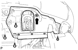
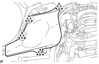
2. REMOVE FRONT FENDER SPLASH SHIELD SUB-ASSEMBLY LH

B180991
  1. Remove the 3 bolts and screw.

  1. Turn the clip indicated by the arrow in the illustration to remove the fender splash shield.


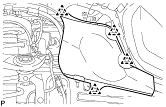
3. REMOVE FRONT FENDER SPLASH SHIELD SUB-ASSEMBLY RH

HINT:
Use the same procedures described for the LH side.


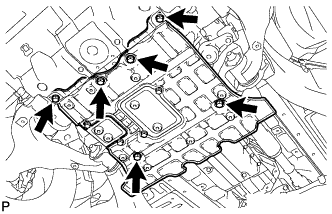
4. REMOVE NO. 2 ENGINE UNDER COVER

C178816
  1. Remove the 6 bolts and under cover.


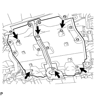
5. REMOVE NO. 1 ENGINE UNDER COVER

C173929
  1. Remove the 6 bolts and under cover.


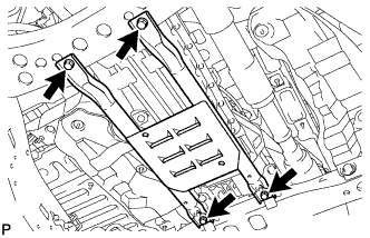
6. REMOVE OIL PAN PROTECTOR ASSEMBLY

C171483
  1. Remove the 4 bolts and oil pan protector.


7. REMOVE FRONT FENDER APRON SEAL FRONT RH

  1. A177003
    Remove the 3 clips and front fender apron seal front RH.


8. REMOVE FRONT FENDER APRON SEAL REAR RH

  1. A177002
    Remove the 4 clips and front fender apron seal rear RH.


9. REMOVE FRONT FENDER APRON SEAL REAR LH

  1. A177005
    Using a clip remover, remove the 4 clips and fender apron seal.


10. DRAIN AUTOMATIC TRANSMISSION FLUID
  1. Remove the drain plug and gasket, and drain the ATF.

  1. Install a new gasket and the drain plug.

    Torque:
    20 N*m{ 204 kgf*cm , 15 ft.*lbf }


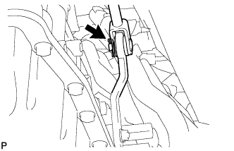
11. DISCONNECT FLOOR SHIFT GEAR SHIFTING ROD SUB-ASSEMBLY

C170828
  1. Remove the clip and pin, and disconnect the gear shifting rod from the transmission control shaft lever RH.


12. REMOVE FRONT PROPELLER SHAFT ASSEMBLY
(Click here)

13. REMOVE PROPELLER SHAFT ASSEMBLY
(Click here)

14. REMOVE EXHAUST PIPE
(Click here)

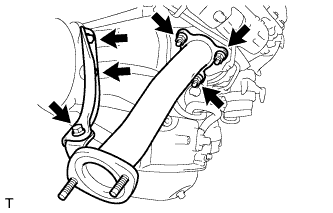
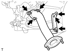
15. REMOVE OUTLET TURBINE ELBOW RH (w/o EGR System)

  1. A174836
    Remove the 3 bolts and manifold stay RH.

  1. Remove the 3 nuts and outlet turbine elbow RH.

  1. Remove the gasket from the turbocharger.


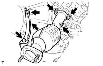
16. REMOVE MONOLITHIC CONVERTER ASSEMBLY RH (w/ EGR System)

  1. A174834
    Remove the 3 bolts and manifold stay RH.

  1. Remove the 3 nuts and monolithic converter RH.

  1. Remove the gasket from the turbocharger.


17. REMOVE OUTLET TURBINE ELBOW LH (w/o EGR System)

  1. A174835
    Remove the 3 bolts and manifold stay LH.

  1. Remove the 3 nuts and outlet turbine elbow LH.

  1. Remove the gasket from the turbocharger.


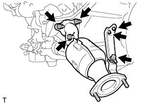
18. REMOVE MONOLITHIC CONVERTER ASSEMBLY LH (w/ EGR System)

  1. A174833
    Remove the 3 bolts and manifold stay LH.

  1. Remove the 3 nuts and monolithic converter LH.

  1. Remove the gasket from the turbocharger.


19. REMOVE DRIVE PLATE AND TORQUE CONVERTER CLUTCH SETTING BOLT

A170323
  1. Remove the 2 bolts and oil pan insulator.

  1. C171531
    Turn the crankshaft to gain access to the 6 bolts and remove the bolts while holding the crankshaft pulley setting bolt with a wrench.


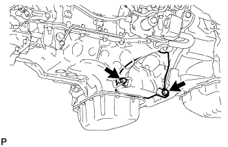
20. DISCONNECT OIL COOLER TUBE

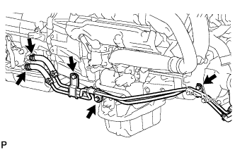
C177423
  1. Disconnect the 2 transmission oil cooler hoses from the oil cooler tube union.

  1. Remove the 3 bolts and separate the oil cooler tube from the engine.


21. SUPPORT AUTOMATIC TRANSMISSION ASSEMBLY

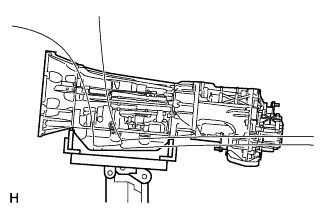
C161356
  1. Support the transmission with a transmission jack. Lift the transmission slightly from the crossmember.


22. REMOVE NO. 2 FRAME CROSSMEMBER SUB-ASSEMBLY

C171484
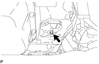
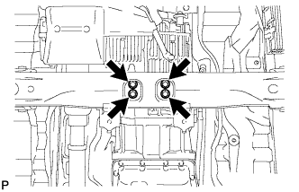
  1. Remove the engine mounting hole cover.

  1. C171489
    Remove the 4 bolts of the rear engine mounting insulator.

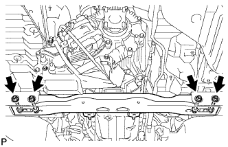
  1. C171490E01
    Remove the 4 nuts, 4 bolts and frame crossmember.


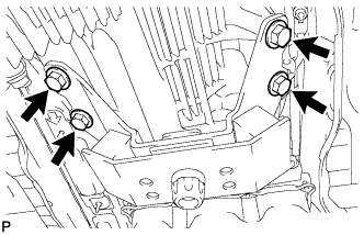
23. REMOVE REAR NO. 1 ENGINE MOUNTING INSULATOR

C172398
  1. Remove the 4 bolts and rear engine mounting insulator from the transmission.


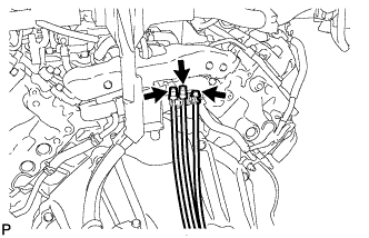
24. DISCONNECT BREATHER PLUG HOSE

C171532
  1. Disconnect the 3 breather plug hoses from the wire harness.


25. DISCONNECT WIRE HARNESS AND CONNECTOR

C171503
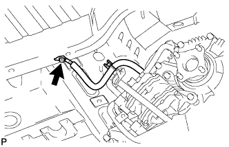
  1. Remove the bolt and disconnect the ground cable.

  1. C162764E01
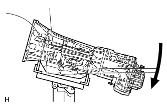
    Tilt the transmission downward.

    NOTICE:
    Make sure the cooling fan does not contact the fan shroud.

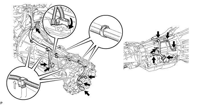
  1. Disconnect the park/neutral position switch connector, 2 transmission wire connectors, 2 speed sensor connectors and 2 or 3 transfer control side connectors.

    C172390E01

    HINT:
    Detach the claw, press down the lever, and then disconnect the transmission wire connector.

  1. Disconnect the 8 harness clamps.

  1. Remove the 2 bolts and disconnect the wire harness.


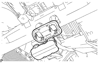
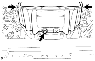
26. REMOVE OIL PAN COVER

C172394
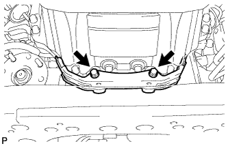
  1. Remove the 2 bolts and oil pan cover.


27. REMOVE TRANSMISSION HOUSING COVER

C175581
  1. Remove the 3 bolts and transmission housing cover.


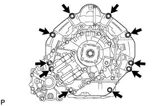
28. REMOVE AUTOMATIC TRANSMISSION ASSEMBLY

C175537
  1. Remove the 10 bolts and transmission.

    NOTICE:
    Do not use excess force to pry off the transmission assembly.


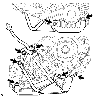
29. REMOVE TRANSFER ASSEMBLY

C171493
  1. Remove the 7 bolts and transfer case lower protector.

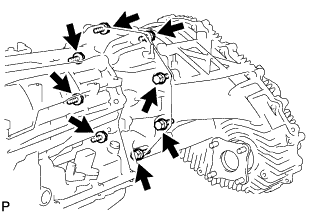
  1. C171523
    Remove the 8 bolts and transfer.


30. REMOVE TORQUE CONVERTER CLUTCH ASSEMBLY

31. INSPECT TORQUE CONVERTER ASSEMBLY
(Click here)
← COMPONENTS (from Jan 2012)REMOVAL (from Jan 2012) →