C1251/51 Open in Pump Motor Circuit
Diagnostic trouble codes · Vehicles built Sep 2011 – Dec 2011
DESCRIPTION
The motor relay (semiconductor relay) is built into the master cylinder solenoid and drives the pump motor based on a signal from the skid control ECU.| DTC Code |
DTC Detection Condition |
Trouble Area |
| C1251/51 |
There is an open in the motor system circuit (motor input circuit). |
|
WIRING DIAGRAM
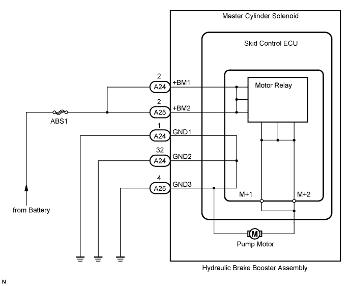

INSPECTION PROCEDURE
- NOTICE:
- When replacing the master cylinder solenoid, perform zero point calibration (Click here).
- HINT:
- Remove the hydraulic brake booster assembly before the inspection (for LHD: Click here/ for RHD: Click here).
| 1. CHECK CONNECTION OF PUMP MOTOR WIRE HARNESS |

Using a screwdriver, remove the 2 plugs from the hydraulic brake booster assembly (for LHD: Click here/ for RHD: Click here).
Check the tightening torque of the 2 screws which tighten the wire harness connecting the hydraulic brake booster assembly and brake booster pump (for LHD: Click here/ for RHD: Click here).
- OK:
- The harness is tightened to the specific torque.
- Torque:
- 2.9 N*m{ 30 kgf*cm , 26 in.*lbf }
|
|
||||

| OK | |
 |
| 2. CHECK RESISTANCE OF PUMP MOTOR WIRE HARNESS |
Using a screwdriver, remove the 2 screws and pull the wire harness from the hydraulic brake booster assembly.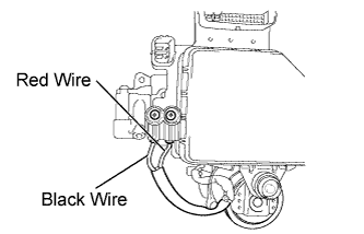
Measure the resistance according to the value(s) in the table below.
- Standard Resistance:
Tester Connection
Condition
Specified Condition
Red wire terminal - Black wire terminal
Always
2 Ω
Result
Proceed to
OK
A
NG
for LHD
B
for RHD
C
|
|
||||
|
|
||||
| A | |
|
| 3. RECONFIRM DTC |
Reassemble the hydraulic brake booster assembly (for LHD: Click here/ for RHD: Click here).
Install the hydraulic brake booster assembly (for LHD: Click here/ for RHD: Click here).
Clear the DTC (Click here).
Check if the same DTC is output (Click here).
Result Result
Proceed to
DTC is not output
A
DTC is output
for LHD
B
for RHD
C
|
|
||||
|
|
||||
| A | ||
 |
||
| ||