C1340/47 Center Differential Lock Circuit
Diagnostic trouble codes · Vehicles built Sep 2011 – Dec 2011
DESCRIPTION
When the center differential is locked, VSC control turns off and "VSC OFF" appears on the multi-information display*1 or the VSC OFF indicator light*2 illuminates.| DTC Code |
DTC Detection Condition |
Trouble Area |
| C1340/47 |
When the terminal IG1 voltage is between 10 and 14 V and there is an open in the center differential lock circuit for 2 seconds or more. |
|
- HINT:
- *1: w/ Multi-information Display
- *2: w/o Multi-information Display
WIRING DIAGRAM
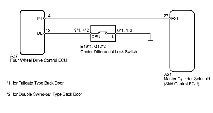

INSPECTION PROCEDURE
- NOTICE:
- When replacing the master cylinder solenoid, perform zero point calibration (Click here).
| 1. INSPECT SKID CONTROL ECU (EXI TERMINAL) |

Set the vehicle in the center differential locked state using the center differential lock switch.
Disconnect the A24 skid control ECU connector.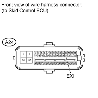
Turn the ignition switch to ON.
Measure the voltage according to the value(s) in the table below.
- Standard Voltage:
Tester Connection
Condition
Specified Condition
A24-27 (EXI) - Body ground
Center differential locked
(Center differential lock switch on)
Below 1.5 V
Connect the A24 skid control ECU connector.
Set the vehicle in the center differential free state using the center differential lock switch.
Disconnect the A24 skid control ECU connector.
Turn the ignition switch to ON.
Measure the voltage according to the value(s) in the table below.
- Standard Voltage:
Tester Connection
Condition
Specified Condition
A24-27 (EXI) - Body ground
Center differential free
(Center differential lock switch off)
11 to 14 V
Result
Proceed to
NG
A
OK
for LHD
B
for RHD
C
|
|
||||
|
|
||||

| A | |
 |
| 2. INSPECT CENTER DIFFERENTIAL LOCK SWITCH |
Remove the center differential lock switch (Click here).
for Tailgate Type Back Door:Measure the resistance according to the value(s) in the table below.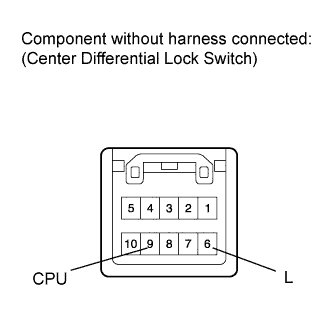
- Standard Resistance:
Tester Connection
Switch Condition
Specified Condition
6 (L) - 9 (CPU)
Switch pressed and held
Below 1 Ω
Switch not pressed
10 kΩ or higher
for Double Swing-out Type Back Door:Measure the resistance according to the value(s) in the table below.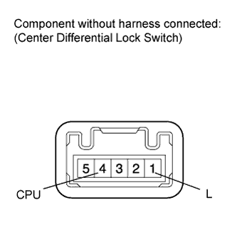
- Standard Resistance:
Tester Connection
Switch Condition
Specified Condition
1 (L) - 4 (CPU)
Switch pressed and held
Below 1 Ω
Switch not pressed
10 kΩ or higher
|
|
||||
| OK | |
|
| 3. INSPECT 4 WHEEL DRIVE CONTROL ECU |
Check the center differential lock system (Click here).
|
|
||||
| OK | |
|
| 4. CHECK HARNESS AND CONNECTOR (FOUR WHEEL DRIVE CONTROL ECU - CENTER DIFFERENTIAL LOCK SWITCH) |
Disconnect the A27 four wheel drive control ECU connector.
for Tailgate Type Back Door:Measure the resistance according to the value(s) in the table below.
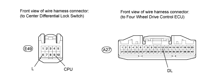
- Standard Resistance:
Tester Connection
Condition
Specified Condition
A27-12 (DL) - E49-9 (CPU)
Always
Below 1 Ω
A27-12 (DL) - Body ground
Always
10 kΩ or higher
E49-6 (L) - Body ground
Always
Below 1 Ω
for Double Swing-out Type Back Door:Measure the resistance according to the value(s) in the table below.
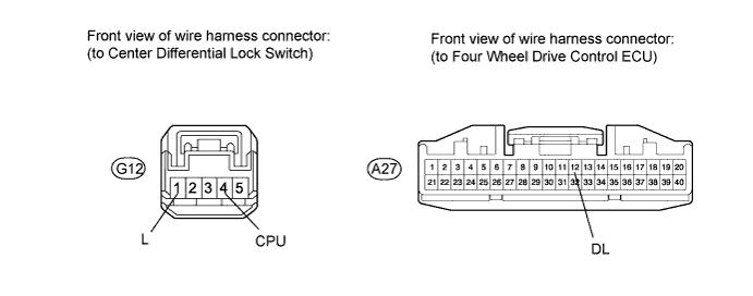
- Standard Resistance:
Tester Connection
Condition
Specified Condition
A27-12 (DL) - G12-4 (CPU)
Always
Below 1 Ω
A27-12 (DL) - Body ground
Always
10 kΩ or higher
G12-1 (L) - Body ground
Always
Below 1 Ω
|
|
||||
| OK | |
|
| 5. CHECK HARNESS AND CONNECTOR (SKID CONTROL ECU - FOUR WHEEL DRIVE CONTROL ECU) |
Disconnect the A24 skid control ECU connector.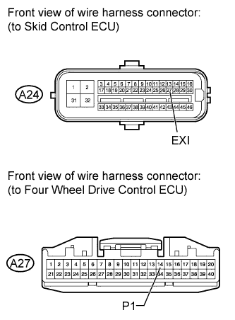
Measure the resistance according to the value(s) in the table below.
- Standard Resistance:
Tester Connection
Condition
Specified Condition
A24-27 (EXI) - A24-14 (P1)
Always
Below 1 Ω
A24-27 (EXI) - Body ground
Always
10 kΩ or higher
Result
Proceed to
NG
A
OK
for LHD
B
for RHD
C
|
|
||||
|
|
||||
| A | ||
 |
||
| ||