REMOVAL
Removal / installation · Vehicles built Sep 2011 – Dec 2011
| 1.
DISCHARGE FUEL SYSTEM PRESSURE
|
 |
Discharge the fuel system pressure (Click here).
| 2.
DISCONNECT CABLE FROM NEGATIVE BATTERY TERMINAL |
|
- CAUTION:
- Wait at least 90 seconds after disconnecting the cable from the negative (-) battery terminal to disable the SRS system.
- NOTICE:
- When disconnecting the cable, some systems need to be initialized after the cable is reconnected (Click here).
| 3.
REMOVE ENGINE ASSEMBLY |
|
Remove the engine assembly from the vehicle (Click here).
| 4.
REMOVE TIMING BELT |
|
Remove the timing belt (Click here).
| 5.
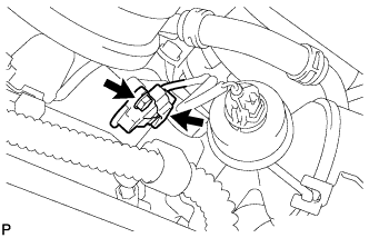
REMOVE CRANKSHAFT POSITION SENSOR
|
|
- Disconnect the sensor connector.
Remove the bolt and sensor.
| 6.
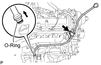
REMOVE ENGINE OIL LEVEL DIPSTICK GUIDE |
|
- Remove the dipstick.
Remove the bolt and dipstick guide.
Remove the O-ring from the dipstick guide.
| 7.
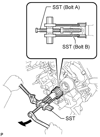
REMOVE CRANKSHAFT TIMING PULLEY |
|
- Using SST, remove the timing pulley.
- SST
- 09950-50013
(09951-05010, 09952-05010, 09953-05010, 09953-05020, 09954-05011)
- HINT:
- Apply a lubricant to the threads and end of SST.
- Parts Number:
Item
|
Parts number
|
SST (Bolt A)
|
09953-05020
|
SST (Bolt B)
|
09953-05010
|
| 8.
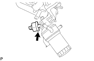
REMOVE OIL PRESSURE SENDER GAUGE ASSEMBLY
|
|
- Disconnect the sender gauge connector.
Remove the sender gauge.
| 9.
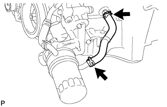
REMOVE OIL COOLER HOSE |
|
- Using needle-nose pliers, grip the claws of the clamps and slide the clamps to remove the oil cooler hose.
| 10.
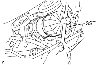
REMOVE OIL FILTER ASSEMBLY
|
|
- Using SST, remove the oil filter.
- SST
- 09228-07501
| 11.
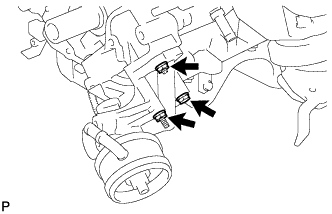
REMOVE OIL FILTER BRACKET SUB-ASSEMBLY |
|
- Remove the bolt, nut, stud bolt, oil filter bracket and gasket.
| 12.
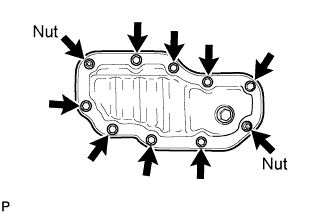
REMOVE NO. 2 OIL PAN SUB-ASSEMBLY |
|
- Remove the 8 bolts and 2 nuts.
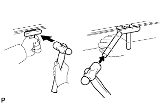
- Insert the blade of an oil pan seal cutter between the oil pans, cut off applied sealer and remove the No. 2 oil pan.
- NOTICE:
- Be careful not to damage the No. 2 oil pan contact surface of the oil pan.
- Be careful not to damage the No. 2 oil pan flange.
| 13.
REMOVE OIL PAN SUB-ASSEMBLY |
|
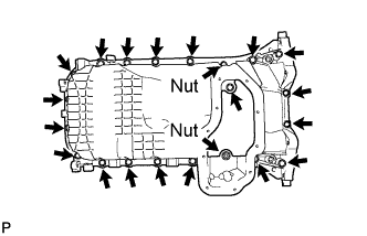
- Remove the 19 bolts and 2 nuts.
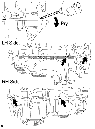
- Using a screwdriver, remove the oil pan by prying between the oil pan and cylinder block as shown in the illustration.
- NOTICE:
- Be careful not to damage the contact surfaces of the cylinder block and oil pan.
| 14.
REMOVE OIL STRAINER SUB-ASSEMBLY |
|
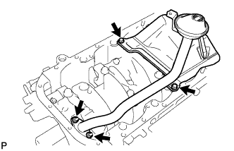
- Remove the 2 bolts, 2 nuts, oil strainer and gasket.
| 15.
REMOVE OIL PUMP ASSEMBLY |
|
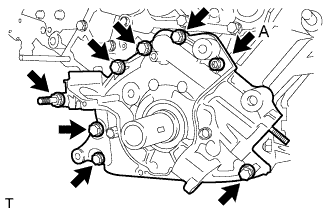
- Using a 6 mm hexagon wrench, remove bolt A.
Remove the 6 bolts and stud bolt.
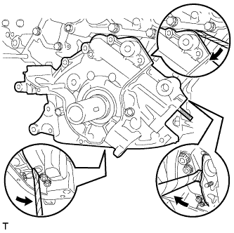
- Using a screwdriver, remove the oil pump by prying the portions between the oil pump and cylinder block shown in the illustration.
- NOTICE:
- Be careful not to damage the contact surfaces of the cylinder block and oil pump.
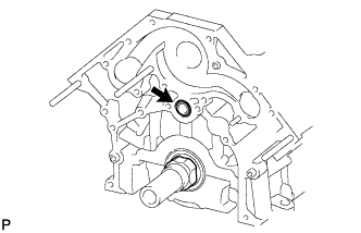
- Remove the O-ring from the cylinder block.