2011-2013 Land Cruiser · Service Manual Power Source / Network

REMOVAL

Removal / installation · Vehicles built from Jan 2012

Versions by build date: Sep 2011 – Dec 2011 from Jan 2012


1. PRECAUTION

NOTICE:
After turning the ignition switch off, waiting time may be required before disconnecting the cable from the battery terminal. Therefore, make sure to read the disconnecting the cable from the battery terminal notice before proceeding with work (Click here).


2. DISCONNECT CABLE FROM NEGATIVE BATTERY TERMINAL

NOTICE:
When disconnecting the cable, some systems need to be initialized after the cable is reconnected (Click here).


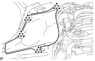
3. REMOVE FRONT FENDER SPLASH SHIELD SUB-ASSEMBLY LH

  1. B310791
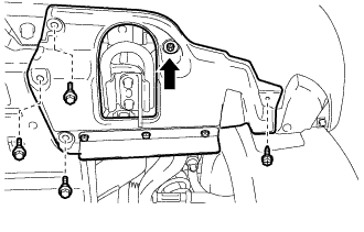
    Remove the 3 bolts and screw.

  1. Turn the clip indicated by the arrow in the illustration to remove the front fender splash shield sub-assembly LH.


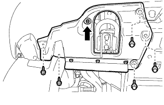
4. REMOVE FRONT FENDER SPLASH SHIELD SUB-ASSEMBLY RH

  1. B310792
    Remove the 3 bolts and 2 screws.

  1. Turn the clip indicated by the arrow in the illustration to remove the front fender splash shield sub-assembly RH.


5. REMOVE NO. 1 ENGINE UNDER COVER SUB-ASSEMBLY

  1. A178461
    Remove the 10 bolts and No. 1 engine under cover.


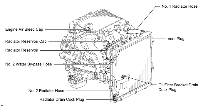
6. DRAIN ENGINE COOLANT

CAUTION:
Do not remove the radiator reservoir cap while the engine and radiator are still hot. Pressurized, hot engine coolant and steam may be released and cause serious burns.

HINT:
Collect the coolant in a container and dispose of it according to the regulations in your area.

  1. Loosen the radiator drain cock plug.

  1. Remove the radiator reservoir cap to drain the coolant in the radiator.

  1. Loosen the oil filter bracket drain cock plug to drain the coolant in the engine.

    A174741E01

  1. Tighten the radiator drain cock plug by hand.

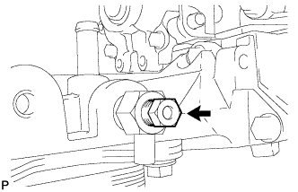
  1. A177208
    Tighten the oil filter bracket drain cock plug.

    Torque:
    13 N*m{ 133 kgf*cm , 10 ft.*lbf }


7. REMOVE FRONT FENDER APRON SEAL FRONT RH

  1. A177003
    Remove the 3 clips and front fender apron seal front RH.


8. REMOVE FRONT FENDER APRON SEAL REAR RH

  1. A177002
    Remove the 4 clips and front fender apron seal rear RH.


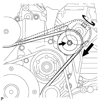
9. REMOVE V-RIBBED BELT (w/ Viscous Heater)

  1. A174847
    Loosen the lock nut and turn the bolt counterclockwise.

  1. Remove the V-ribbed belt.


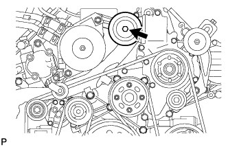
10. REMOVE NO. 1 IDLER PULLEY (w/ Viscous Heater)

  1. A177430
    Remove the bolt, cover, No. 1 idler pulley and collar.


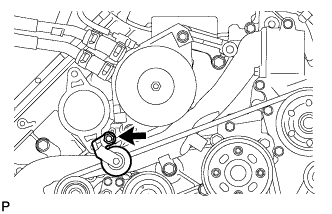
11. REMOVE NO. 3 IDLER PULLEY (w/ Viscous Heater)

  1. A177431
    Remove the nut and No. 3 idler pulley.


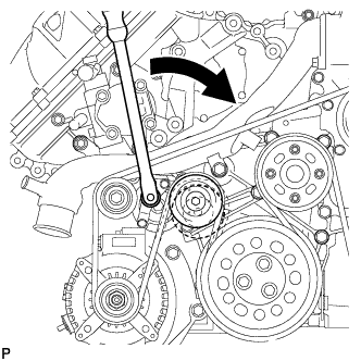
12. REMOVE V-RIBBED BELT

  1. A174849
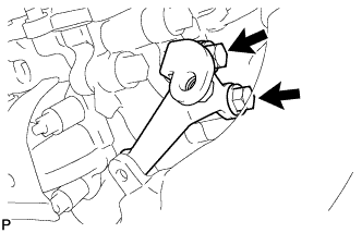
    Using a wrench to the V-ribbed belt tensioner bracket, turn the wrench clockwise and remove the V-ribbed belt.

13. REMOVE INTERCOOLER ASSEMBLY (w/ Intercooler)
(Click here)

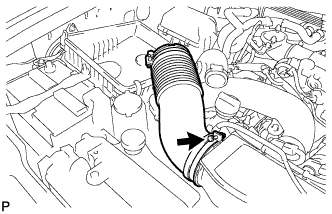
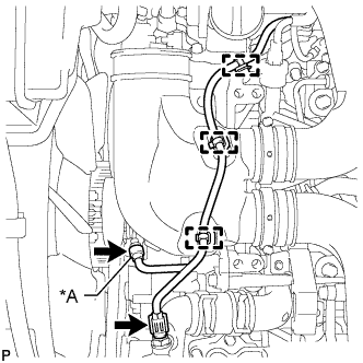
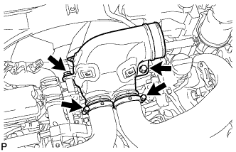
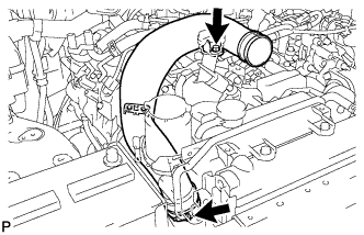
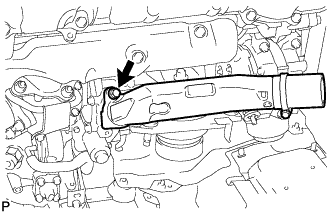
14. REMOVE NO. 1 COOL AIR INLET (w/o Intercooler)

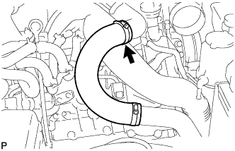
  1. A257026
    Loosen the No. 1 air hose clamp.

  1. Disconnect the turbo pressure sensor connector, intake air temperature sensor connector and vacuum hose.

  1. A257028
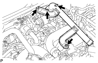
    Remove the 3 nuts, bolt and No. 1 cool air inlet.

  1. Remove the gasket from the air tube RH.


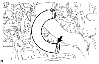
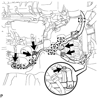
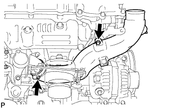
15. REMOVE NO. 2 COOL AIR INLET (w/o Intercooler)

  1. A257027
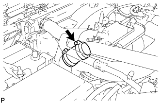
    Loosen the No. 2 air hose clamp.

  1. A257029
    Remove the 3 nuts, bolt and No. 2 cool air inlet.

  1. Remove the gasket from the air tube LH.


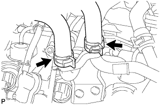
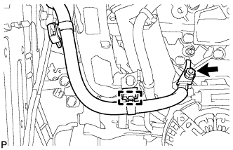
16. DISCONNECT WATER HOSE SUB-ASSEMBLY (w/ Viscous Heater)

  1. A179014E01
    Disconnect the 2 water hoses.


17. REMOVE NO. 2 ENGINE OIL LEVEL DIPSTICK GUIDE

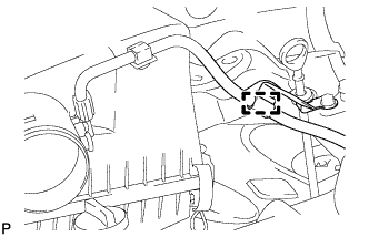
  1. A174875
    Disconnect the wire harness clamp from the No. 2 engine oil level dipstick guide.

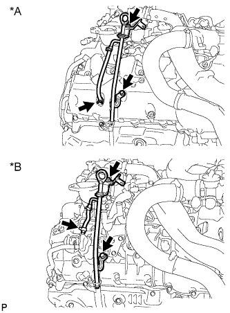
  1. A267228E01
    Disconnect the ventilation hose from the cylinder head cover RH.
    Text in Illustration 
    *A
    w/ DPF
    *B
    w/o DPF

  1. Remove the 2 bolts and No. 2 engine oil level dipstick guide.

  1. Remove the O-ring from the No. 2 engine oil level dipstick guide.


18. REMOVE AIR CLEANER CAP SUB-ASSEMBLY

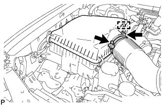
  1. A174698
    Loosen the hose clamp.

  1. Disconnect the mass air flow meter connector and using a clip remover, detach the wire harness clamp from the air cleaner cap.

  1. Detach the 4 clamps and remove the air cleaner cap.


19. REMOVE NO. 1 AIR CLEANER HOSE

  1. A174699
    Loosen the hose clamp and remove the No. 1 air cleaner hose.


20. REMOVE INTAKE AIR CONNECTOR

  1. A174749E04
    w/ Viscous Heater:
    Disconnect the 2 connectors from the viscous with magnet clutch heater and water temperature sensor.
    Text in Illustration 
    *A
    w/ Viscous Heater

  1. w/o Viscous Heater:
    Disconnect the connector from the water temperature sensor.

  1. Using a clip remover, detach the 3 wire harness clamps.

  1. A174710
    Loosen the 2 hose clamps and remove the 2 bolts and intake air connector.


21. REMOVE NO. 1 AIR HOSE

  1. A177374
    Loosen the hose clamp and remove the No. 1 air hose.


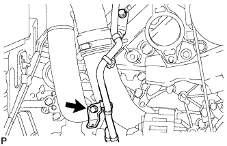
22. REMOVE NO. 3 AIR TUBE

  1. A174751
    Disconnect the wire harness from the clamp.

  1. Remove the nut and ground wire.

  1. A174752
    Remove the bolt and disconnect the wire harness bracket.

  1. A174708
    Loosen the hose clamp and remove the bolt and No. 3 air tube.


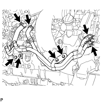
23. REMOVE HEATER WATER PIPE SUB-ASSEMBLY (w/ Viscous Heater)

  1. A174689
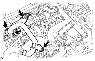
    Remove the 4 bolts and disconnect the 4 water hose ends, and then remove the heater water pipe.


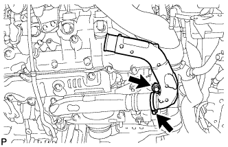
24. REMOVE NO. 1 AIR CLEANER PIPE SUB-ASSEMBLY

  1. A174714
    Loosen the hose clamp.

  1. Remove the bolt and No. 1 air cleaner pipe.


25. REMOVE NO. 1 AIR TUBE ASSEMBLY

  1. A174709
    Remove the bolt and No. 1 air tube.

  1. Remove the O-ring.


26. REMOVE GENERATOR ASSEMBLY
  1. Disconnect the 4 connectors.

  1. A178941
    Disconnect the 6 wire harness clamps.

  1. Remove the terminal cap.

  1. Remove the nut and disconnect the generator wire.

  1. Remove the bolt and disconnect the wire harness bracket from the belt tensioner.

  1. A185246
    Loosen the clamp and remove the bolt.

  1. A180129
    Remove the 2 bolts and No. 1 intake air connector bracket.

  1. Remove the No. 1 intake air connector pipe from the No. 1 inlet compressor elbow.

  1. A163034
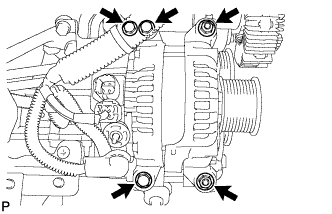
    Remove the 3 bolts and 2 nuts.

  1. Using an E7 "TORX" socket wrench, remove the 2 stud bolts and generator.

← REMOVAL (Sep 2011 – Dec 2011)DISASSEMBLY (from Sep 2011) →