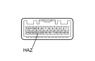
Hazard Warning Switch Circuit
Circuit diagnosis · Vehicles built from Jan 2012
Versions by build date: Sep 2011 – Dec 2011 from Jan 2012
DESCRIPTION
The turn signal flasher receives a hazard warning signal switch information signal, and illuminates the turn signal lights.WIRING DIAGRAM
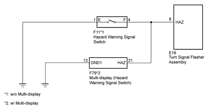

INSPECTION PROCEDURE
| 1. CHECK VEHICLE TYPE |
 |
Check the vehicle type.
Result
Result
|
Proceed to
|
w/o Multi-display
|
A
|
w/ Multi-display
|
B
|
|
B |
 |
|
|
|
| A |
|
 |
|
| 2. INSPECT HAZARD WARNING SIGNAL SWITCH |
|
Remove the hazard warning signal switch (Click here).
Inspect the hazard warning signal switch (Click here).
|
NG |
 |
|
|
|
| OK |
|
|
|
| 3. CHECK HARNESS AND CONNECTOR (HAZARD WARNING SIGNAL SWITCH - TURN SIGNAL FLASHER ASSEMBLY AND BODY GROUND) |
|
Disconnect the F11 hazard warning signal switch connector.
Disconnect the E19 turn signal flasher connector.
Measure the resistance according to the value(s) in the table below.
- Standard Resistance:
Tester Connection
|
Condition
|
Specified Condition
|
F11-4 (F) - E19-8 (HAZ)
|
Always
|
Below 1 Ω
|
F11-1 (E) - Body ground
|
F11-4 (F) - Body ground
|
Always
|
10 kΩ or higher
|
|
NG |
|
|
| REPAIR OR REPLACE HARNESS OR CONNECTOR |
|
|
| OK |
|
 |
|
| PROCEED TO NEXT SUSPECTED AREA SHOWN IN PROBLEM SYMPTOMS TABLE (Click here)
|
|
| 4. INSPECT MULTI-DISPLAY (HAZARD WARNING SIGNAL SWITCH) |
|
- Remove the multi-display (Click here).
Measure the resistance according to the value(s) in the table below.
- Standard Resistance:
Tester Connection
|
Switch Condition
|
Specified Condition
|
21 (HAZ) - Body ground (Multi-display body ground)
|
Hazard warning switch on
|
Below 1 Ω
|
Hazard warning switch off
|
10 kΩ or higher
|
|
NG |
|
|
| REPLACE MULTI-DISPLAY (HAZARD WARNING SIGNAL SWITCH) (Click here)
|
|
|
| OK |
|
|
|
| 5. CHECK HARNESS AND CONNECTOR (MULTI-DISPLAY [HAZARD WARNING SIGNAL SWITCH] - TURN SIGNAL FLASHER ASSEMBLY AND BODY GROUND) |
|
Disconnect the F79 multi-display connector.
Disconnect the E19 turn signal flasher connector.
Measure the resistance according to the value(s) in the table below.
- Standard Resistance:
Tester Connection
|
Condition
|
Specified Condition
|
F79-21 (HAZ) - E19-8 (HAZ)
|
Always
|
Below 1 Ω
|
F79-13 (GND1) - Body ground
|
F79-21 (HAZ) - Body ground
|
Always
|
10 kΩ or higher
|
|
NG |
|
|
| REPAIR OR REPLACE HARNESS OR CONNECTOR |
|
|
| OK |
|
|
|
| PROCEED TO NEXT SUSPECTED AREA SHOWN IN PROBLEM SYMPTOMS TABLE (Click here)
|
|