Home › Steering › STEERING GEAR / LINKAGE › STEERING LINKAGEREMOVAL
Removal / installation · Vehicles built from Jan 2012
Versions by build date: Sep 2011 – Dec 2011 from Jan 2012
CAUTION:
Some of these service operations affect the SRS airbag system. Read the precautionary notices concerning the SRS airbag system before servicing the steering column (Click here ).
1.
PLACE FRONT WHEELS FACING STRAIGHT AHEAD
2.
REMOVE ENGINE ASSEMBLY
for 1UZ-FE: Remove the engine (Click here ).
for 1GR-FE: Remove the engine (Click here ).
for 1VD-FTV: Remove the engine (Click here ).
for 3UR-FE: Remove the engine (Click here ).
4.
LOOSEN NO. 1 FRONT STABILIZER BRACKET LH
w/ KDSS: Loosen the bracket (Click here ).
w/o KDSS: Loosen the bracket (Click here ).
5.
LOOSEN NO. 1 FRONT STABILIZER BRACKET RH
HINT:
Use the same procedures described for the LH side.
6.
REMOVE FRONT STABILIZER LINK ASSEMBLY LH
w/ KDSS: Remove the front stabilizer link (Click here ).
w/o KDSS: Remove the front stabilizer link (Click here ).
7.
REMOVE FRONT STABILIZER LINK ASSEMBLY RH
HINT:
Use the same procedures described for the LH side.
8.
REMOVE FRONT NO. 1 STABILIZER BRACKET LH
w/ KDSS: Remove the stabilizer bracket (Click here ).
w/o KDSS: Remove the front bracket (Click here ).
9.
REMOVE FRONT NO. 1 STABILIZER BRACKET RH
HINT:
Use the same procedures described for the LH side.
10.
REMOVE FRONT STABILIZER BAR
w/ KDSS: Remove the stabilizer bar (Click here ).
w/o KDSS: Remove the stabilizer bar (Click here ).
11.
DISCONNECT NO. 2 STEERING INTERMEDIATE SHAFT
for Manual Tilt and Telescopic: Disconnect the No. 2 steering intermediate shaft (Click here ).
for Power Tilt and Power Telescopic: Disconnect the No. 2 steering intermediate shaft (Click here ).
12.
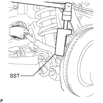
DISCONNECT TIE ROD END SUB-ASSEMBLY LH
Remove the cotter pin and nut.
Using SST, disconnect the tie rod end LH from the steering knuckle.
SST
09610-20012
NOTICE:
Do not damage the front disc brake dust cover.
Do not damage the ball joint dust cover.
Do not damage the steering knuckle.
13.
DISCONNECT TIE ROD END SUB-ASSEMBLY RH
HINT:
Use the same procedures described for the LH side.
14.
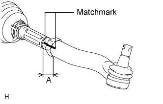
REMOVE TIE ROD END SUB-ASSEMBLY LH
Put matchmarks on the tie rod end LH and steering rack end. Measure length A and record the measurement.
Remove the tie rod end LH.
15.
REMOVE TIE ROD END SUB-ASSEMBLY RH
HINT:
Use the same procedures described for the LH side.
16.
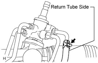
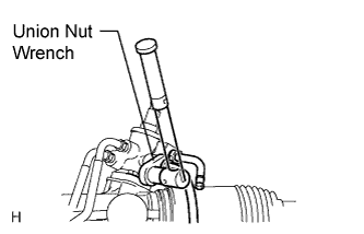
DISCONNECT PRESSURE FEED TUBE ASSEMBLY
Remove the clamp and disconnect the pressure feed tube (return tube side) from the power steering link.
Using a union nut wrench, disconnect the pressure feed tube (pressure feed tube side) from the power steering link.
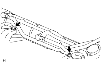
Remove the 2 bolts and disconnect the pressure feed tube clamp.
17.
REMOVE FRONT SUSPENSION REBOUND STOPPER SUB-ASSEMBLY LH
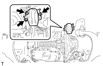
Remove the 3 bolts and suspension rebound stopper LH.
18.
REMOVE FRONT SUSPENSION REBOUND STOPPER SUB-ASSEMBLY RH
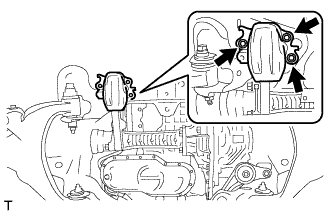
Remove the 3 bolts and suspension rebound stopper RH.
19.
REMOVE POWER STEERING LINK ASSEMBLY
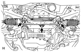
Remove the 3 bolts, 3 nuts and power steering link.