Home › Engine / Hybrid / EV System › CRUISE CONTROL › CRUISE CONTROL SYSTEMClutch Switch Circuit
Circuit diagnosis · Vehicles built from Jan 2012
Versions by build date: Sep 2011 – Dec 2011 from Jan 2012
DESCRIPTION
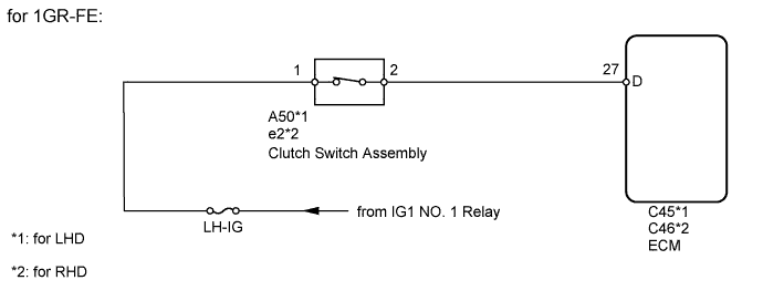
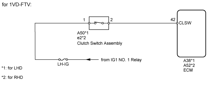
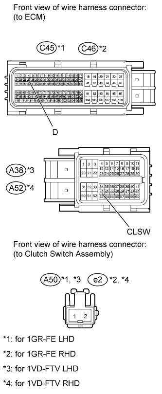
When the clutch pedal is released, the ECM receives positive (+) battery voltage through the LH-IG fuse. While depressing the clutch pedal, the clutch switch sends a signal to terminal D*1 or CLSW*2 of the ECM. The ECM cancels cruise control when terminal D*1 or CLSW*2 receives the signal.
HINT:
*1: for 1GR-FE
*2: for 1VD-FTV
WIRING DIAGRAM
INSPECTION PROCEDURE
1. INSPECT FUSE (LH-IG)
Remove the LH-IG fuse from the main body ECU.
Measure the resistance according to the value(s) in the table below.
Standard Resistance:
Tester Connection
Condition
Specified Condition
LH-IG fuse
Always
Below 1 Ω
NG
OK
2. CHECK HARNESS AND CONNECTOR (ECM - BATTERY)
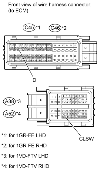
Disconnect the C45*1, C46*2, A38*3 or A52*4 ECM connector.
HINT:
*1: for 1GR-FE LHD
*2: for 1GR-FE RHD
*3: for 1VD-FTV LHD
*4: for 1VD-FTV RHD
Measure the voltage according to the value(s) in the table below.
Standard Voltage:
for 1GR-FE LHD
Tester Connection
Switch Condition
Specified Condition
C45-27 (D) - Body ground
Ignition switch ON
Below 1 V
Ignition switch ON
11 to 14 V
for 1GR-FE RHD
Tester Connection
Switch Condition
Specified Condition
C46-27 (D) - Body ground
Ignition switch ON
Below 1 V
Ignition switch ON
11 to 14 V
for 1VD-FTV LHD
Tester Connection
Switch Condition
Specified Condition
A38-42 (CLSW) - Body ground
Ignition switch ON
Below 1 V
Ignition switch ON
11 to 14 V
for 1VD-FTV RHD
Tester Connection
Switch Condition
Specified Condition
A52-42 (CLSW) - Body ground
Ignition switch ON
Below 1 V
Ignition switch ON
11 to 14 V
NG
OK
PROCEED TO NEXT CIRCUIT INSPECTION SHOWN IN PROBLEM SYMPTOMS TABLE (Click here )
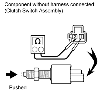
3. INSPECT CLUTCH SWITCH ASSEMBLY
Turn the ignition switch off. Remove the clutch switch assembly (Click here for LHD, Click here for RHD).
Measure the resistance according to the value(s) in the table below.
Standard Resistance:
Tester Connection
Switch Condition
Specified Condition
1 - 2
Pushed (On)
Below 1 Ω
Not pushed (Off)
10 kΩ or higher
Result
Result
Proceed to
OK
A
NG (for LHD)
B
NG (for RHD)
C
Install the clutch switch assembly (Click here for LHD, Click here for RHD).
B
C
A
4. CHECK HARNESS AND CONNECTOR (ECM - CLUTCH SWITCH ASSEMBLY)
Disconnect the C45*1, C46*2, A38*3 or A52*4 ECM connector.
HINT:
*1: for 1GR-FE LHD
*2: for 1GR-FE RHD
*3: for 1VD-FTV LHD
*4: for 1VD-FTV RHD
Disconnect the A50*1 or e2*2 clutch switch assembly connector.
HINT:
*1: for LHD
*2: for RHD
Measure the resistance according to the value(s) in the table below.
Standard Resistance:
for 1GR-FE LHD
Tester Connection
Condition
Specified Condition
C45-27 (D) - A50-2
Always
Below 1 Ω
C45-27 (D) - Body ground
Always
10 kΩ or higher
for 1GR-FE RHD
Tester Connection
Condition
Specified Condition
C46-27 (D) - e2-2
Always
Below 1 Ω
C46-27 (D) - Body ground
Always
10 kΩ or higher
for 1VD-FTV LHD
Tester Connection
Condition
Specified Condition
A38-42 (CLSW) - A50-2
Always
Below 1 Ω
A38-42 (CLSW) - Body ground
Always
10 kΩ or higher
for 1VD-FTV RHD
Tester Connection
Condition
Specified Condition
A52-42 (CLSW) - e2-2
Always
Below 1 Ω
A52-42 (CLSW) - Body ground
Always
10 kΩ or higher
NG
REPAIR OR REPLACE HARNESS OR CONNECTOR (ECM - CLUTCH SWITCH ASSEMBLY)
OK
REPAIR OR REPLACE HARNESS OR CONNECTOR (BATTERY - CLUTCH SWITCH ASSEMBLY)