Engine does not Start but Initial Combustion Occurs
Circuit diagnosis · Vehicles built Sep 2011 – Dec 2011
Versions by build date: Sep 2011 – Dec 2011 from Jan 2012
DESCRIPTION
The key ID code of the transponder chip inside the IG key is compared against the key ID code registered in the transponder key ECU assembly. While checking the code, the transponder key ECU assembly supplies electrical power to the transponder chip in the key by means of the transponder key amplifier. If the codes match, the immobiliser is then UNSET (released), and after the engine start permission signal is sent to the ECM, if communication is functioning properly, engine start can be performed.WIRING DIAGRAM
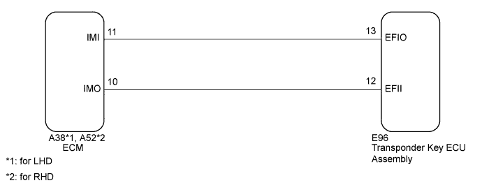

INSPECTION PROCEDURE
- NOTICE:
- When replacing the key and transponder key ECU assembly, refer to the Service Bulletin.
| 1. CHECK FOR DTC |

Check for DTCs (Click here).
- HINT:
- Before checking for DTCs, perform the "DTC Output Confirmation Operation" procedure.
Result Result
Proceed to
No DTC output
A
DTC output
B
|
|
||||

| A | |
 |
| 2. CONFIRM ENGINE MODEL |
Check the vehicle specifications.
Result Result
Proceed to
1GR-FE
A
1VD-FTV
B
|
|
||||

| A | |
|
| 3. READ VALUE USING INTELLIGENT TESTER |
Turn the ignition switch off.
Connect the intelligent tester to the DLC3.
Turn the ignition switch to ON.
Turn the intelligent tester on.
Enter the following menus: Powertrain / Engine and ECT / Data List.
Engine and ECT Tester Display
Measurement Item/Range
Normal Condition
Stored as Freeze Frame Data
Immobiliser Fuel Cut
Status of immobiliser fuel cut/
ON or OFF
-
Yes
- OK:
- The item in the Data List indicates "OFF".
|
|
||||
| OK | ||
 |
||
| ||
| 4. CHECK WHETHER ENGINE STARTS |
Turn the ignition switch to ON, wait for 5 seconds, and then attempt to start the engine.
Result Result
Proceed to
Engine cannot be started
A
Engine can be started
B
|
|
||||
| A | |
|
| 5. CHECK ECM (TERMINAL IMI) |
Using an oscilloscope, check the waveform.
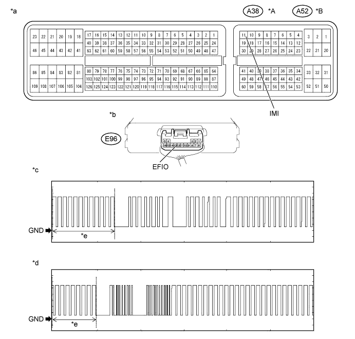
Text in Illustration *A
for LHD
*B
for RHD
*a
Component with harness connected
(ECM)
*b
Component with harness connected
(Transponder Key ECU Assembly)
*c
Waveform 1
*d
Waveform 2
*e
Waveform A
-
-
Measurement Condition Item
Content
Tester Connection
A38-11 (IMI) - E96-13 (EFIO)*1
A52-11 (IMI) - E96-13 (EFIO)*2
Tool Setting
2 V/DIV., 500 ms./DIV.
Condition
Within 3 seconds after starter operates and initial combustion occurs, or within 3 seconds after ignition switch first turned to ON after battery disconnected and reconnected
- *1: for LHD
- *2: for RHD
- HINT:
- The waveform shown in the illustration is an example for reference only. Noise, chattering, etc. are not shown.
- OK:
- Waveform is output normally (refer to illustration).
Result Result
Proceed to
Normal waveform
A
Waveform 1 or 2 (Waveform A) not output, or has abnormal wavelength or shape
B
- *1: for LHD
|
|
||||
| A | |
|
| 6. CHECK ECM (TERMINAL IMO) |
Using an oscilloscope, check the waveform.
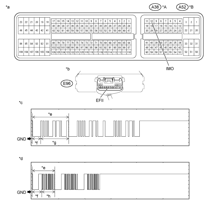
Text in Illustration *A
for LHD
*B
for RHD
*a
Component with harness connected
(ECM)
*b
Component with harness connected
(Transponder Key ECU Assembly)
*c
Waveform 1
*d
Waveform 2
*e
Waveform B
*f
160 ms
*g
510 ms
*h
270 ms
Measurement Condition Item
Content
Tester Connection
A38-10 (IMO) - E96-12 (EFII)*1
A52-10 (IMO) - E96-12 (EFII)*2
Tool Setting
2 V/DIV., 500 ms./DIV.
Condition
Within 3 seconds after starter operates and initial combustion occurs, or within 3 seconds after ignition switch first turned to ON after battery disconnected and reconnected
- *1: for LHD
- *2: for RHD
- HINT:
- The waveform shown in the illustration is an example for reference only. Noise, chattering, etc. are not shown.
- OK:
- Waveform is output normally (refer to illustration).
Result Result
Proceed to
Normal waveform
A
Waveform 1 or 2 (Waveform B) not output, or has abnormal wavelength or shape (for 1GR-FE)
B
Waveform 1 or 2 (Waveform B) not output, or has abnormal wavelength or shape (for 1VD-FTV)
C
- *1: for LHD
|
|
||||
|
|
||||
| A | |
|
| 7. CHECK ECM (TERMINAL IMI) |
Using an oscilloscope, check the waveform.
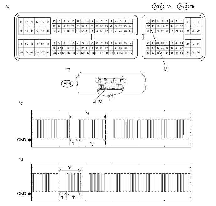
Text in Illustration *A
for LHD
*B
for RHD
*a
Component with harness connected
(ECM)
*b
Component with harness connected
(Transponder Key ECU Assembly)
*c
Waveform 1
*d
Waveform 2
*e
Waveform C
*f
160 ms
*g
510 ms
*h
270 ms
Measurement Condition Item
Content
Tester Connection
A38-11 (IMI) - E96-13 (EFIO)*1
A52-11 (IMI) - E96-13 (EFIO)*2
Tool Setting
2 V/DIV., 500 ms./DIV.
Condition
Within 3 seconds after starter operates and initial combustion occurs, or within 3 seconds after ignition switch first turned to ON after battery disconnected and reconnected
- *1: for LHD
- *2: for RHD
- HINT:
- The waveform shown in the illustration is an example for reference only. Noise, chattering, etc. are not shown.
- OK:
- Waveform is output normally (refer to illustration).
Result Result
Proceed to
Normal waveform
A
Waveform 1 or 2 (Waveform C) not output, or has abnormal wavelength or shape
B
- *1: for LHD
|
|
||||
| A | |
|
| 8. REGISTER ECU COMMUNICATION ID |
Register the ECU communication ID (refer to the Service Bulletin).
| NEXT | |
|
| 9. CHECK WHETHER ENGINE STARTS |
Check that the engine starts with the key.
- OK:
- Engine starts normally.
|
|
||||
| OK | ||
|
||
| ||
| 10. CHECK HARNESS AND CONNECTOR (ECM - TRANSPONDER KEY ECU ASSEMBLY) |
for LHD:
Disconnect the A38 ECM connector.
Disconnect the E96 transponder key ECU assembly connector.
Measure the resistance according to the value(s) in the table below.
- Standard Resistance:
Tester Connection
Condition
Specified Condition
A38-11 (IMI) - E96-13 (EFIO)
Always
Below 1 Ω
E96-13 (EFIO) - Body ground
Always
10 kΩ or higher
for RHD:
Disconnect the A52 ECM connector.
Disconnect the E96 transponder key ECU assembly connector.
Measure the resistance according to the value(s) in the table below.
- Standard Resistance:
Tester Connection
Condition
Specified Condition
A52-11 (IMI) - E96-13 (EFIO)
Always
Below 1 Ω
E96-13 (EFIO) - Body ground
Always
10 kΩ or higher
|
|
||||
| OK | |
|
| 11. REPLACE TRANSPONDER KEY ECU ASSEMBLY |
Replace the transponder key ECU assembly.
Check that the engine starts with the key.
- OK:
- Engine starts normally.
Result Result
Proceed to
OK
A
NG (for 1GR-FE)
B
NG (for 1VD-FTV)
C
|
|
||||
|
|
||||
| A | ||
|
||
| ||