Home › Engine / Hybrid System › 1VD-FTV (ENGINE CONTROL) › ECD SYSTEM (w/o DPF) › 2014.08–2015.08
RM2660E _51 Engine / Hybrid System _052773 1VD-FTV ENGINE CONTROL _0254984 ECD SYSTEM(w/o DPF) J

1VD-FTV ENGINE CONTROL  ECD SYSTEM(w/o DPF)  Injector Circuit  


DESCRIPTION

The injector driver drives the injectors at high speeds with a high-voltage DC/DC converter. The ECM constantly monitors the injector driver and stops the engine if an abnormal condition is detected.

PROCEDURE

1.CHECK EDU (POWER SOURCE)

OK

REPLACE INJECTOR DRIVER (No. 1 or No. 2)

NG

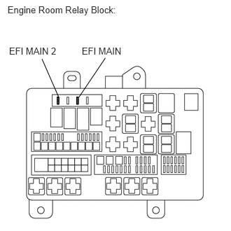
2.INSPECT FUSE (EFI)
A182599E01
0.112,0.066 1.980,0.254 1.869,0.188 10 Engine Room Relay Block: 0.135,0.673 0.905,0.838 0.770,0.165 10 EFI MAIN 2 1.217,0.673 1.875,0.838 0.658,0.165 10 EFI MAIN 0.869,1.436 0.624,0.876 false 1.172,1.449 1.567,0.863 false

a.

Remove the EFI MAIN and EFI MAIN 2 fuse from the engine room relay block.


b.

Measure the resistance according to the value(s) in the table below.

Standard Resistance:
Tester Connection Condition Specified Condition
EFI MAIN fuse Always Below 1 Ω
EFI MAIN 2 fuse Always Below 1 Ω


OK

3.INSPECT EDU RELAY (EDU 1 OR EDU 2)

NG

CHECK FOR SHORTS IN ALL HARNESSES AND CONNECTORS CONNECTED TO FUSE AND REPLACE FUSE

3.INSPECT EDU RELAY (EDU 1 OR EDU 2)
a.

Inspect the EDU relay (EDU 1 or EDU 2) (See page Engine / Hybrid System>1VD-FTV (ENGINE CONTROL)>RELAY>ON-VEHICLE INSPECTION).


OK

4.INSPECT INTEGRATION NO.1 RELAY (EFI OR EFI MAIN 2)

NG

REPLACE EDU RELAY (EDU 1 OR EDU 2)

4.INSPECT INTEGRATION NO.1 RELAY (EFI OR EFI MAIN 2)
a.

Inspect the Integration relay (EFI or EFI MAIN 2) (See page Engine / Hybrid System>1VD-FTV (ENGINE CONTROL)>RELAY>ON-VEHICLE INSPECTION).


OK

5.CHECK HARNESS AND CONNECTOR (EDU RELAY - EDU)

NG

REPLACE INTEGRATION NO.1 RELAY

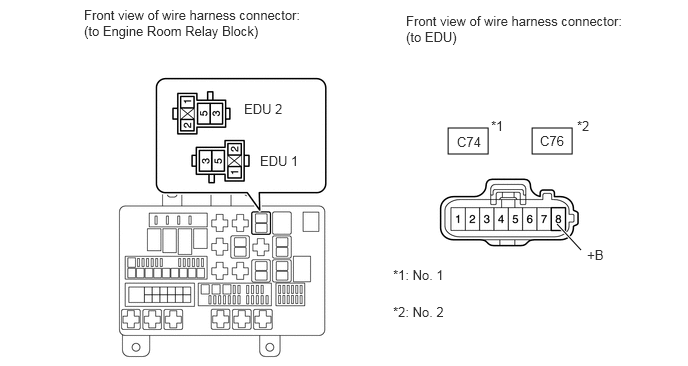
5.CHECK HARNESS AND CONNECTOR (EDU RELAY - EDU)
A385310E01
4.667,1.333 5.083,1.604 0.417,0.271 5.542,1.333 5.958,1.604 0.417,0.271 6.052,2.604 5.802,2.333 true 0.875,0.073 3.167,0.438 2.292,0.365 10 false Front view of wire harness connector: (to Engine Room Relay Block) 4.229,0.135 6.521,0.5 2.292,0.365 10 false Front view of wire harness connector: (to EDU) 4.76,1.396 5.083,1.573 0.323,0.177 10 false C74 5.625,1.385 5.948,1.563 0.323,0.177 10 false C76 5.115,1.229 5.333,1.427 0.219,0.198 10 false *1 6.01,1.229 6.229,1.427 0.219,0.198 10 false *2 6.115,2.573 6.438,2.75 0.323,0.177 10 false +B 4.094,2.781 4.802,2.99 0.708,0.208 10 false *1: No. 1 4.094,3.167 4.802,3.375 0.708,0.208 10 false *2: No. 2 2.542,1.052 3.094,1.26 0.552,0.208 10 false EDU 2 2.708,1.594 3.25,1.802 0.542,0.208 10 false EDU 1

a.

Remove the EDU relay (EDU 1 or EDU 2) from the engine room relay block.


b.

Remove the EDU connector.


c.

Measure the resistance according to the value(s) in the table below.

Standard Resistance (Check for Open):
No. 1
Tester Connection Condition Specified Condition
EDU 1 relay (5) - C74-8 (+B) Always Below 1 Ω

No. 2
Tester Connection Condition Specified Condition
EDU 2 relay (5) - C76-8 (+B) Always Below 1 Ω

Standard Resistance (Check for Short):
No. 1
Tester Connection Condition Specified Condition
EDU 1 relay (5) or C74-8 (+B) - Body ground Always 10 kΩ or higher

No. 2
Tester Connection Condition Specified Condition
EDU 2 relay (5) or C76-8 (+B) - Body ground Always 10 kΩ or higher


OK

6.CHECK HARNESS AND CONNECTOR (EDU RELAY - ECM)

NG

REPAIR OR REPLACE HARNESS OR CONNECTOR

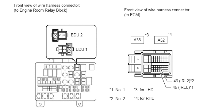
6.CHECK HARNESS AND CONNECTOR (EDU RELAY - ECM)
A384948E01
4.448,1.229 4.885,1.49 0.438,0.26 5.25,1.229 5.677,1.49 0.427,0.26 5.448,2.333 5.677,2.76 5.677,2.76 5.833,2.76 true 5.385,2.333 5.635,2.969 5.635,2.969 5.802,2.969 true 0.469,0.094 2.781,0.458 2.313,0.365 10 false Front view of wire harness connector: (to Engine Room Relay Block) 2.406,1.104 3.177,1.302 0.771,0.198 10 false EDU 2 2.573,1.594 3.344,1.792 0.771,0.198 10 false EDU 1 4.219,0.25 6.531,0.615 2.313,0.365 10 false Front view of wire harness connector: (to ECM) 4.542,1.271 4.979,1.5 0.438,0.229 10 false A38 5.354,1.281 5.792,1.51 0.438,0.229 10 false A52 4.927,1.104 5.167,1.313 0.24,0.208 10 false *3 5.708,1.083 5.948,1.292 0.24,0.208 10 false *4 5.896,2.667 6.656,2.906 0.76,0.24 10 false 46 (IRL2)*2 5.865,2.885 6.625,3.125 0.76,0.24 10 false 45 (IREL)*1 3.719,2.969 4.479,3.208 0.76,0.24 10 false *1: No. 1 3.719,3.271 4.479,3.51 0.76,0.24 10 false *2: No. 2 4.542,2.969 5.302,3.208 0.76,0.24 10 false *3: for LHD 4.552,3.26 5.313,3.5 0.76,0.24 10 false *4: for RHD

a.

Remove the EDU relay (EDU 1 or EDU 2) from the engine room relay block.


b.

Disconnect the ECM connector.


c.

Measure the resistance according to the value(s) in the table below.

Standard Resistance (Check for Open):
No. 1 (LHD)
Tester Connection Condition Specified Condition
EDU 1 relay (2) - A38-45 (IREL) Always Below 1 Ω

No. 2 (LHD)
Tester Connection Condition Specified Condition
EDU 2 relay (2) - A38-46 (IRL2) Always Below 1 Ω

No. 1 (RHD)
Tester Connection Condition Specified Condition
EDU 1 relay (2) - A52-45 (IREL) Always Below 1 Ω

No. 2 (RHD)
Tester Connection Condition Specified Condition
EDU 2 relay (2) - A52-46 (IRL2) Always Below 1 Ω

Standard Resistance (Check for Short):
No. 1 (LHD)
Tester Connection Condition Specified Condition
EDU 1 relay (2) or A38-45 (IREL) - Body ground Always 10 kΩ or higher

No. 2 (LHD)
Tester Connection Condition Specified Condition
EDU 2 relay (2) or A38-46 (IRL2) - Body ground Always 10 kΩ or higher

No. 1 (RHD)
Tester Connection Condition Specified Condition
EDU 1 relay (2) or A52-45 (IREL) - Body ground Always 10 kΩ or higher

No. 2 (RHD)
Tester Connection Condition Specified Condition
EDU 2 relay (2) or A52-46 (IRL2) - Body ground Always 10 kΩ or higher


OK

7.CHECK HARNESS AND CONNECTOR (INTEGRATION RELAY - EDU RELAY, ECM, BODY GROUND)

NG

REPAIR OR REPLACE HARNESS OR CONNECTOR

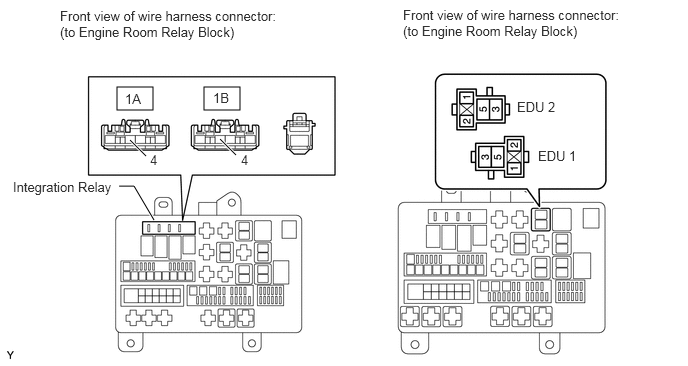
7.CHECK HARNESS AND CONNECTOR (INTEGRATION RELAY - EDU RELAY, ECM, BODY GROUND)
A384960E01
1.219,0.906 1.594,1.146 0.375,0.24 2.125,0.906 2.5,1.146 0.375,0.24 1.354,1.458 1.521,1.625 true 2.292,1.448 2.458,1.615 true 1.24,1.938 1.396,1.938 1.396,1.938 1.604,2.292 true 0.625,0.083 2.938,0.458 2.313,0.375 10 false Front view of wire harness connector: (to Engine Room Relay Block) 4.198,0.073 6.51,0.448 2.313,0.375 10 false Front view of wire harness connector: (to Engine Room Relay Block) 1.302,0.948 1.615,1.146 0.313,0.198 10 false 1A 2.219,0.938 2.531,1.135 0.313,0.198 10 false 1B 1.563,1.583 1.74,1.75 0.177,0.167 10 false 4 2.51,1.583 2.688,1.75 0.177,0.167 10 false 4 0.135,1.865 1.25,2.052 1.115,0.188 10 false Integration Relay 5.385,1.031 5.927,1.219 0.542,0.188 10 false EDU 2 5.604,1.542 6.146,1.729 0.542,0.188 10 false EDU 1

a.

Remove the integration relay from the engine room relay block.


b.

Remove the EDU relay (EDU 1 or EDU 2).


c.

Measure the resistance according to the value(s) in the table below.

Standard Resistance (Check for Open):
No. 1
Tester Connection Condition Specified Condition
1B-4 - EDU 1 relay (1) Always Below 1 Ω
1B-4 - EDU 1 relay (3) Always Below 1 Ω

No. 2
Tester Connection Condition Specified Condition
1A-4 - EDU 2 relay (1) Always Below 1 Ω
1A-4 - EDU 2 relay (3) Always Below 1 Ω

Standard Resistance (Check for Short):
No. 1
Tester Connection Condition Specified Condition
1B-4 or EDU 1 relay (1) - Body ground Always 10 kΩ or higher
1B-4 or EDU 1 relay (3) - Body ground Always 10 kΩ or higher

No. 2
Tester Connection Condition Specified Condition
1A-4 or EDU 2 relay (1) - Body ground Always 10 kΩ or higher
1A-4 or EDU 2 relay (3) - Body ground Always 10 kΩ or higher


A384963E01
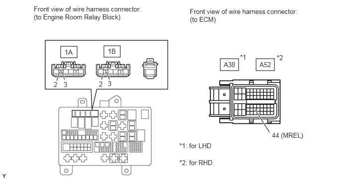
1.271,0.969 1.615,1.208 0.344,0.24 2.177,0.958 2.521,1.198 0.344,0.24 4.615,1.229 5,1.479 0.385,0.25 5.365,1.229 5.75,1.479 0.385,0.25 1.188,1.688 1.25,1.5 true 1.354,1.667 1.292,1.5 true 2.125,1.667 2.177,1.51 true 2.292,1.667 2.229,1.5 true 5.646,2.771 5.344,2.292 true 0.708,0.104 3.01,0.469 2.302,0.365 10 false Front view of wire harness connector: (to Engine Room Relay Block) 3.979,0.156 6.281,0.521 2.302,0.365 10 false Front view of wire harness connector: (to ECM) 1.354,1.01 1.667,1.208 0.313,0.198 10 false 1A 2.26,0.99 2.573,1.188 0.313,0.198 10 false 1B 1.333,1.688 1.458,1.854 0.125,0.167 10 false 3 1.125,1.688 1.25,1.854 0.125,0.167 10 false 2 2.073,1.677 2.198,1.844 0.125,0.167 10 false 2 2.26,1.667 2.385,1.833 0.125,0.167 10 false 3 4.688,1.271 5,1.469 0.313,0.198 10 false A38 5.438,1.271 5.75,1.469 0.313,0.198 10 false A52 5.031,1.115 5.24,1.302 0.208,0.188 10 false *1 5.802,1.125 6.01,1.313 0.208,0.188 10 false *2 5.698,2.75 6.5,2.958 0.802,0.208 10 false 44 (MREL) 3.76,2.969 4.563,3.177 0.802,0.208 10 false *1: for LHD 3.76,3.323 4.563,3.531 0.802,0.208 10 false *2: for RHD

d.

Disconnect the ECM connector.


e.

Measure the resistance according to the value(s) in the table below.

Standard Resistance (Check for Open):
No. 1 (LHD)
Tester Connection Condition Specified Condition
1B-2 - A38-44 (MREL) Always Below 1 Ω
1B-3 - Body ground Always Below 1 Ω

No. 2 (LHD)
Tester Connection Condition Specified Condition
1A-2 - A38-44 (MREL) Always Below 1 Ω
1A-3 - Body ground Always Below 1 Ω

No. 1 (RHD)
Tester Connection Condition Specified Condition
1B-2 - A52-44 (MREL) Always Below 1 Ω
1B-3 - Body ground Always Below 1 Ω

No. 2 (RHD)
Tester Connection Condition Specified Condition
1A-2 - A52-44 (MREL) Always Below 1 Ω
1A-3 - Body ground Always Below 1 Ω

Standard Resistance (Check for Short):
No. 1 (LHD)
Tester Connection Condition Specified Condition
1B-2 or A38-44 (MREL) - Body ground Always 10 kΩ or higher

No. 2 (LHD)
Tester Connection Condition Specified Condition
1A-2 or A38-44 (MREL) - Body ground Always 10 kΩ or higher

No. 1 (RHD)
Tester Connection Condition Specified Condition
1B-2 or A52-44 (MREL) - Body ground Always 10 kΩ or higher

No. 2 (RHD)
Tester Connection Condition Specified Condition
1A-2 or A52-44 (MREL) - Body ground Always 10 kΩ or higher


OK

8.CHECK HARNESS AND CONNECTOR (EDU - BODY GROUND)

NG

REPAIR OR REPLACE HARNESS OR CONNECTOR

8.CHECK HARNESS AND CONNECTOR (EDU - BODY GROUND)
a.
U162947E01
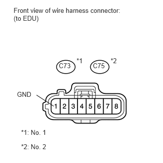
0.287,0.133 2.641,0.459 2.354,0.326 10 Front view of wire harness connector: (to EDU) 1.239,1.305 1.520,1.461 0.281,0.156 10 C73 1.614,1.202 1.770,1.357 0.156,0.156 10 *1 0.445,2.711 1.050,2.867 0.605,0.156 10 *1: No. 1 0.445,3.015 1.050,3.171 0.605,0.156 10 *2: No. 2 1.958,1.305 2.240,1.461 0.282,0.156 10 C75 2.333,1.202 2.489,1.357 0.156,0.156 10 *2 0.357,1.909 0.718,2.084 0.361,0.175 10 GND 1.134,2.24 0.769,2.004 false

Disconnect the EDU connector.


b.

Measure the resistance according to the value(s) in the table below.

Standard Resistance:
No. 1
Tester Connection Condition Specified Condition
C73-1 (GND) - Body ground Always Below 1 Ω


Standard Resistance:
No. 2
Tester Connection Condition Specified Condition
C75-1 (GND) - Body ground Always Below 1 Ω


OK

NG

REPAIR OR REPLACE HARNESS OR CONNECTOR (EDU - BODY GROUND)