1VD-FTV ENGINE CONTROL DIESEL THROTTLE BODY INSTALLATION
CAUTION / NOTICE / HINT
- NOTICE:
-
Disconnect the cable from the negative (-) battery terminal to clear the diesel throttle valve fully closed position learned value.
PROCEDURE

 1.INSTALL DIESEL THROTTLE BODY ASSEMBLY LH
Install a new gasket to the intake pipe.
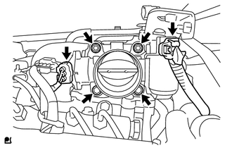
Install the throttle body with the 2 bolts and 2 nuts.
- Torque:
- 21 N*m (214 kgf*cm, 15 ft.*lbf)
Connect the throttle position sensor connector.
Connect the throttle motor connector.
26100G
2.INSTALL DIESEL THROTTLE BODY ASSEMBLY RH
Install a new gasket to the intake pipe.
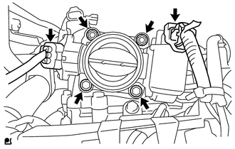
Install the throttle body with the 2 bolts and 2 nuts.
- Torque:
- 21 N*m (214 kgf*cm, 15 ft.*lbf)
Connect the throttle position sensor connector.
Connect the throttle motor connector.
31489
3.INSTALL TUBE CONNECTOR TO FLEXIBLE HOSE TUBE (for Manual Transmission)
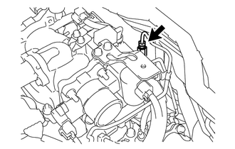
Temporarily install the flare nut of the tube connector to flexible hose tube to the clutch tube to release cylinder 2 way by hand.
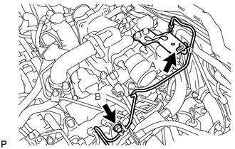
Temporarily install the tube connector to flexible hose tube with the 2 bolts.
Tighten the bolt labeled A.
- Torque:
- 20 N*m (204 kgf*cm, 15 ft.*lbf)
- NOTICE:
-
Tighten the bolt labeled B after installing the clutch hose.
17972
4.INSTALL AIR TUBE SUB-ASSEMBLY LH
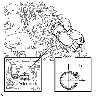
Install the air tube to the throttle body.
Align the embossed mark of the throttle body with the paint mark of the No. 4 air hose.
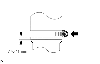
Tighten the hose clamp so that it is 7 to 11 mm (0.276 to 0.433 in.) from the end of the hose as shown in the illustration.
- Torque:
- 6.3 N*m (64 kgf*cm, 56 in.*lbf)
31418
5.INSTALL CLUTCH HOSE (for Manual Transmission)
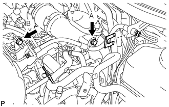
Connect the clutch hose to the air tube with the bolt labeled A.
Temporarily install the clutch hose to the clutch master cylinder tube to flexible hose tube and tube connector to flexible hose tube, and fix it in place with the 2 clips.
- Torque:
- 20 N*m (204 kgf*cm, 15 ft.*lbf)
Tighten the bolt labeled B.
- Torque:
- 20 N*m (204 kgf*cm, 15 ft.*lbf)
Tighten the flexible hose tube.
- NOTICE:
- ·
Do not bend or damage the flexible hose tube.
·Do not allow any foreign matter such as dirt and dust to enter the flexible hose tube from the connecting points.
- HINT:
- ·
Use a torque wrench with a fulcrum length of 30 cm (11.8 in.). If using a torque wrench with a length that is not 30 cm (11.8 in.), calculate the torque specification for the torque wrench and SST based on the "without SST" torque specification (See page General>INTRODUCTION>REPAIR INSTRUCTION>PRECAUTION).
·Make sure union nut wrench and the wrench are connected in a straight line.
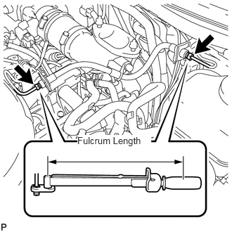
Using a 10 mm union nut wrench, tighten the 2 flare nuts of the flexible hose tube.
- Torque:
- without union nut wrench : 15 N*m (154 kgf*cm, 11 ft.*lbf)
- with union nut wrench : 14 N*m (141 kgf*cm, 10 ft.*lbf)
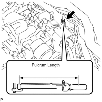
Using a 10 mm union nut wrench, tighten the flare nut of the flexible hose tube.
- Torque:
- without union nut wrench : 15 N*m (154 kgf*cm, 11 ft.*lbf)
- with union nut wrench : 14 N*m (141 kgf*cm, 10 ft.*lbf)
17971
6.INSTALL AIR TUBE SUB-ASSEMBLY RH
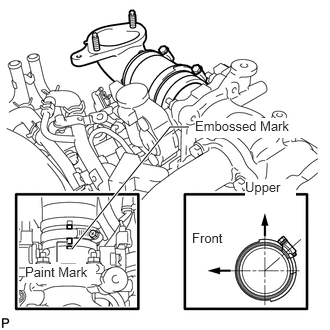
Install the air tube to the throttle body.
Align the embossed mark of the throttle body with the paint mark of the No. 4 air hose.
Tighten the hose clamp so that it is 7 to 11 mm (0.276 to 0.433 in.) from the end of the hose as shown in the illustration.
- Torque:
- 6.3 N*m (64 kgf*cm, 56 in.*lbf)
12142
7.CONNECT NO. 2 ENGINE OIL LEVEL DIPSTICK GUIDE
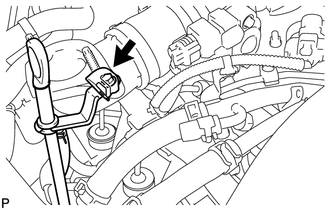
Connect the dipstick guide with the bolt.
- Torque:
- 10 N*m (102 kgf*cm, 7 ft.*lbf)
8.INSTALL NO. 1 COOL AIR INLET (w/o Intercooler)
9.INSTALL NO. 2 COOL AIR INLET (w/o Intercooler)
17940D
10.INSTALL INTERCOOLER ASSEMBLY (w/ Intercooler)
11.FILL BRAKE FLUID RESERVOIR
12.BLEED CLUTCH LINE
13.CHECK FLUID LEVEL IN RESERVOIR
14.INSPECT FOR CLUTCH FLUID LEAK
15.CONNECT CABLE TO NEGATIVE BATTERY TERMINAL
- NOTICE:
-
When disconnecting the cable, some systems need to be initialized after the cable is reconnected (See page General>INTRODUCTION>REPAIR INSTRUCTION>INITIALIZATION).
16.CHECK DIESEL THROTTLE BODY ASSEMBLY
17.PERFORM DIESEL THROTTLE BODY INITIALIZATION