3UR-FE ENGINE MECHANICAL CYLINDER HEAD GASKET INSTALLATION
PROCEDURE

 11101A
1.INSPECT CYLINDER HEAD SET BOLT
11101
2.INSPECT CYLINDER HEAD SUB-ASSEMBLY
11101
3.INSTALL CYLINDER HEAD SUB-ASSEMBLY RH
Clean the cylinder block with solvent.
Set the piston of the No. 1 cylinder to slightly ATDC.
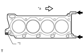
Place the cylinder head gasket on the cylinder block surface with the front face of the Lot No. stamp upward.
| *1 | Lot No. |
| *a | Front |
- NOTICE:
- ·
Be careful of the installation direction.
·Make sure that no oil is on the front end (indicated by the arrows) of the cylinder head gasket.
Place the cylinder head on the cylinder block.
- NOTICE:
- ·
Ensure that no oil is on the mounting surface of the cylinder head.
·Gently place the cylinder head in order not to damage the gasket with the bottom part of the head.
- HINT:
-
The cylinder head bolts are tightened in 3 progressive steps.
Apply a light coat of engine oil to the threads and under the heads of the cylinder head bolts.
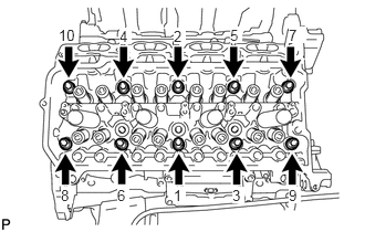
Step 1:
Using a 10 mm bi-hexagon wrench, install and uniformly tighten the 10 cylinder head bolts with the plate washers in several steps in the sequence shown in the illustration.
- Torque:
- 36 N*m (367 kgf*cm, 27 ft.*lbf)
Step 2:
Mark the front side of each cylinder head bolt head with paint.
Tighten the cylinder head bolts another 90°.
Step 3:
Tighten the cylinder head bolts an additional 90°.
Check that the paint marks are now at a 180° angle to the front.
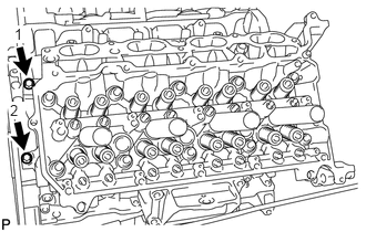
Install and uniformly tighten the 2 bolts in the sequence shown in the illustration.
- Torque:
- 21 N*m (214 kgf*cm, 15 ft.*lbf)
11102
4.INSTALL CYLINDER HEAD SUB-ASSEMBLY LH
Clean the cylinder block with solvent.
Set the piston of the No. 1 cylinder to slightly ATDC.
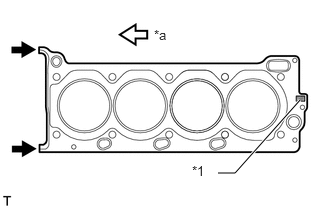
Place the cylinder head gasket on the cylinder block surface with the front face of the Lot No. stamp upward.
| *1 | Lot No. |
| *a | Front |
- NOTICE:
- ·
Be careful of the installation direction.
·Make sure that no oil is on the front end (indicated by the arrows) of the cylinder head gasket.
Place the cylinder head on the cylinder block.
- NOTICE:
- ·
Ensure that no oil is on the mounting surface of the cylinder head.
·Gently place the cylinder head in order not to damage the gasket with the bottom part of the head.
- HINT:
-
The cylinder head bolts are tightened in 3 progressive steps.
Apply a light coat of engine oil to the threads and under the heads of the cylinder head bolts.
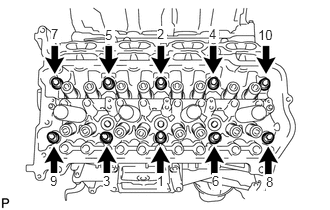
Step 1:
- HINT:
-
The cylinder head bolts are tightened in 3 progressive steps.
Using a 10 mm bi-hexagon wrench, install and uniformly tighten the 10 cylinder head bolts with the plate washers in several steps in the sequence shown in the illustration.
- Torque:
- 36 N*m (367 kgf*cm, 27 ft.*lbf)
Step 2:
Mark the front side of each cylinder head bolt head with paint.
Tighten the cylinder head bolts another 90°.
Step 3:
Tighten the cylinder head bolts an additional 90°.
Check that the paint marks are now at a 180° angle to the front.
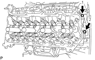
Install and uniformly tighten the 2 bolts in the sequence shown in the illustration.
- Torque:
- 21 N*m (214 kgf*cm, 15 ft.*lbf)
13716
5.INSTALL VALVE STEM CAP
13750
6.INSTALL VALVE LASH ADJUSTER ASSEMBLY
13801
7.INSTALL NO. 1 VALVE ROCKER ARM SUB-ASSEMBLY
13511
8.INSTALL CAMSHAFT
17105
9.INSTALL EXHAUST MANIFOLD SUB-ASSEMBLY