3UR-FE FUEL FUEL TANK INSTALLATION
PROCEDURE

 77697
1.INSTALL NO. 1 FUEL TANK HEAT INSULATOR
Install the No. 1 fuel tank heat insulator with the 4 clips.
Install the fuel tube clamp to the No. 1 fuel tank heat insulator.
77213B
2.INSTALL FUEL TANK TO FILLER PIPE HOSE
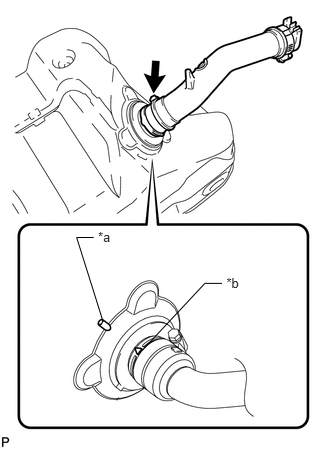
Install the fuel tank to filler pipe hose to the fuel tank sub-assembly as shown in the illustration and tighten the hose clamp.
| *a | Fuel Tank Side Mark |
| *b | Hose Side Mark |
- HINT:
- ·
Align the fuel tank side mark with the hose side mark when installing the hose.
·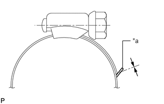 2.777,0.77 2.981,0.952 0.203,0.183 10 *a 2.736,0.858 2.57,0.858 2.57,0.858 2.57,1.44 false
Tighten the hose clamp until the end of the hose clamp contacts the stopper as shown in the illustration.
| *a | Stopper |
77020A
3.INSTALL FUEL SUCTION WITH PUMP AND GAUGE TUBE ASSEMBLY
4.INSTALL FUEL TANK MAIN TUBE, FUEL TANK RETURN TUBE AND NO. 2 FUEL TANK MAIN TUBE SUB-ASSEMBLY
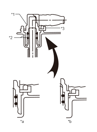
Install the 3 fuel tank tubes with the 3 tube joint clips.
- NOTICE:
- ·
Check that there are no scratches or foreign objects on the connecting parts.
·Check that the fuel tube joints are inserted securely.
·Check that the tube joint clips are on the collars of the fuel tube joints.
·After installing the tube joint clips, check that the fuel tube joints cannot be pulled off.
| *1 | Fuel Tube Joint |
| *2 | O-Ring |
| *3 | Tube Joint Clip |
| *a | CORRECT |
| *b | INCORRECT |
for G.C.C. Countries:
Attach the 2 clamps and install the No. 2 fuel tank main tube sub-assembly.
Attach the clamp and install the fuel tank return tube sub-assembly.
Attach the clamp and install the fuel tank main tube sub-assembly.
except G.C.C. Countries:
Attach the 2 clamps and install the No. 2 fuel tank main tube sub-assembly.
Attach the clamp and install the fuel tank return tube sub-assembly.
Attach the clamp and install the fuel tank main tube sub-assembly.
77259E
5.CONNECT FUEL HOSE
for G.C.C. Countries:
Install the fuel hose to the fuel suction tube sub-assembly, and slide the clip to secure the hose.
77100U
6.INSTALL FUEL TANK SUB-ASSEMBLY
Set the fuel tank sub-assembly on an engine lifter and raise the fuel tank sub-assembly.
- NOTICE:
-
Do not allow the fuel tank sub-assembly to contact the vehicle, especially the differential.
Raise the engine lifter.
Install the 2 fuel tank band sub-assemblies with the 2 pins and 2 clips.
Connect the 2 fuel tank band sub-assemblies with the 2 bolts.
- Torque:
- 40 N*m (408 kgf*cm, 30 ft.*lbf)
7.CONNECT FUEL TANK TO FILLER PIPE HOSE
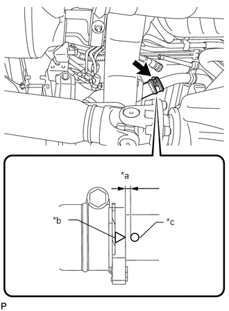
Connect the fuel tank to filler pipe hose to the fuel tank to filler pipe sub-assembly as shown in the illustration and tighten the hose clamp.
| *a | 0 to 0.3 mm (0 to 0.0118 in.) |
| *b | Fuel Tank to Filler Pipe Hose Side Mark |
| *c | Fuel Tank Inlet Pipe Side Mark |
- HINT:
- ·
Install the hose so that the distance between the fuel tank inlet pipe side mark and fuel tank to filler pipe hose side mark is 0 to 0.3 mm (0 to 0.0118 in.) as shown in the illustration.
·
2.777,0.77 2.981,0.952 0.203,0.183 10 *a 2.736,0.858 2.57,0.858 2.57,0.858 2.57,1.44 false
Tighten the hose clamp until the end of the hose clamp contacts the stopper as shown in the illustration.
| *a | Stopper |
8.CONNECT FUEL TANK BREATHER TUBE
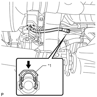
Connect the fuel tank breather tube to the fuel tank to filler pipe sub-assembly and push the retainer.
| *1 | Retainer |

|
Push |
- NOTICE:
- ·
Before installing the tube connectors to the pipes, check if there is any damage or foreign matter in the connectors.
·After the connection, check if the connectors and pipes are securely connected by trying to pull them apart.
- HINT:
-
Push the parts together firmly until a "click" sound is heard.
Attach the fuel tube clamp.
9.CONNECT NO. 2 FUEL TANK BREATHER TUBE
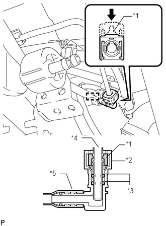
except G.C.C. Countries:
Connect the No. 2 fuel tank breather tube and push the retainer.
- NOTICE:
- ·
Before installing the tube connectors to the pipes, check if there is any damage or foreign matter in the connectors.
·After the connection, check if the connectors and pipes are securely connected by trying to pull them apart.
| *1 | Retainer |
| *2 | Connector |
| *3 | O-Ring |
| *4 | Pipe |
| *5 | Nylon Tube |
|
|
Push |
- HINT:
-
Push the parts together firmly until a "click" sound is heard.
Attach the fuel tube clamp.
77206C
10.CONNECT NO. 2 FUEL TANK MAIN TUBE SUB-ASSEMBLY
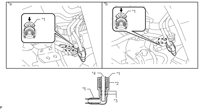
| *1 | Retainer | *2 | Connector |
| *3 | O-Ring | *4 | Pipe |
| *5 | Nylon Tube | - | - |
| *a | except G.C.C. Countries | *b | for G.C.C. Countries |
|
|
Push | - | - |
Connect the No. 2 fuel tank main tube sub-assembly and push the retainer.
- NOTICE:
- ·
Before installing the tube connectors to the pipes, check if there is any damage or foreign matter in the connectors.
·After the connection, check if the connectors and pipes are securely connected by trying to pull them apart.
- HINT:
-
Push the parts together firmly until a "click" sound is heard.
Attach the fuel tube clamp.
77259E
11.CONNECT FUEL HOSE
for G.C.C. Countries:
Connect the fuel hose to the pipe, and slide the clip to secure the hose.
Attach the fuel tube clamp.
77027B
12.CONNECT NO. 1 FUEL EMISSION TUBE SUB-ASSEMBLY
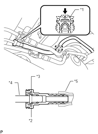
except G.C.C. Countries:
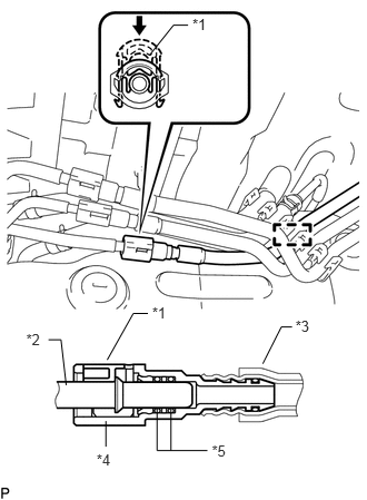
Connect the No. 1 fuel emission tube sub-assembly and push the retainer.
- NOTICE:
- ·
Before installing the tube connectors to the pipes, check if there is any damage or foreign matter in the connectors.
·After the connection, check if the connectors and pipes are securely connected by trying to pull them apart.
| *1 | Retainer |
| *2 | Connector |
| *3 | O-Ring |
| *4 | Pipe |
| *5 | Nylon Tube |
|
|
Push |
- HINT:
-
Push the parts together firmly until a "click" sound is heard.
Attach the fuel tube clamp.
for G.C.C. Countries:
Connect the No. 1 fuel emission tube sub-assembly and push the retainer.
- NOTICE:
- ·
Before installing the tube connectors to the pipes, check if there is any damage or foreign matter in the connectors.
·After the connection, check if the connectors and pipes are securely connected by trying to pull them apart.
| *1 | Retainer |
| *2 | Pipe |
| *3 | Nylon Tube |
| *4 | Connector |
| *5 | O-Ring |
|
|
Push |
- HINT:
-
Push the parts together firmly until a "click" sound is heard.
Attach the fuel tube clamp.
13.CONNECT FUEL TANK RETURN TUBE
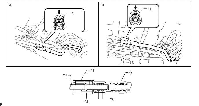
| *1 | Retainer | *2 | Pipe |
| *3 | Nylon Tube | *4 | Connector |
| *5 | O-Ring | - | - |
| *a | except G.C.C. Countries | *b | for G.C.C. Countries |
|
|
Push | - | - |
Connect the fuel tank return tube and push the retainer.
- NOTICE:
- ·
Before installing the tube connectors to the pipes, check if there is any damage or foreign matter in the connectors.
·After the connection, check if the connectors and pipes are securely connected by trying to pull them apart.
- HINT:
-
Push the parts together firmly until a "click" sound is heard.
Attach the fuel tube clamp.
14.CONNECT NO. 2 FUEL TANK BREATHER HOSE
for G.C.C. Countries:
Connect the No. 2 fuel tank breather hose to the pipe, and slide the clip to secure the hose.
Attach the fuel pipe clamp.
15.CONNECT FUEL TANK MAIN TUBE SUB-ASSEMBLY
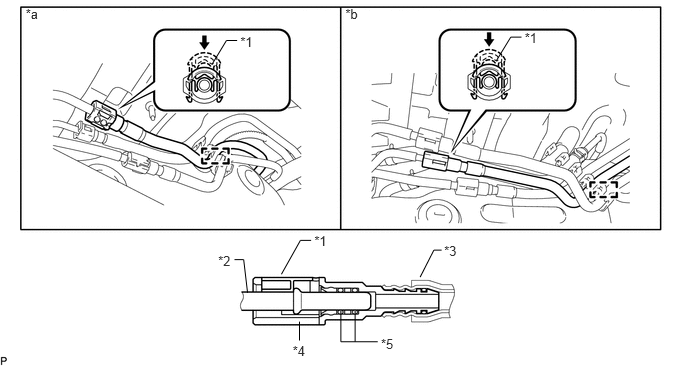
| *1 | Retainer | *2 | Pipe |
| *3 | Nylon Tube | *4 | Connector |
| *5 | O-Ring | - | - |
| *a | except G.C.C. Countries | *b | for G.C.C. Countries |
|
|
Push | - | - |
Connect the fuel tank main tube sub-assembly and push the retainer.
- NOTICE:
- ·
Before installing the tube connectors to the pipes, check if there is any damage or foreign matter in the connectors.
·After the connection, check if the connectors and pipes are securely connected by trying to pull them apart.
- HINT:
-
Push the parts together firmly until a "click" sound is heard.
Attach the fuel tube clamp.
77606
16.INSTALL NO. 1 FUEL TANK PROTECTOR SUB-ASSEMBLY
Install the No. 1 fuel tank protector sub-assembly with the 5 bolts.
- Torque:
- 20 N*m (204 kgf*cm, 15 ft.*lbf)
77310A
17.INSTALL FUEL TANK CAP ASSEMBLY
58329F
18.INSTALL REAR FLOOR NO. 2 SERVICE HOLE COVER
Connect the fuel pump and fuel sender gauge connector.
Install the rear floor No. 2 service hole cover with new butyl tape.
Install the air duct and 2 screws.
58510D
19.INSTALL FRONT FLOOR CARPET ASSEMBLY
20.INSTALL REAR NO. 2 SEAT ASSEMBLY
for Face to Face Seat Type:
Install the rear No. 2 seat assembly (See page Vehicle Interior>SEAT>REAR NO. 2 SEAT ASSEMBLY(for Face to Face Seat Type)>INSTALLATION).
except Face to Face Seat Type:
Install the rear No. 2 seat assembly (See page Vehicle Interior>SEAT>REAR NO. 2 SEAT ASSEMBLY(except Face to Face Seat Type)>INSTALLATION).
71400S
21.INSTALL REAR NO. 1 SEAT ASSEMBLY LH (for 60/40 Split Seat Type 60 Side)
71300S
22.INSTALL REAR NO. 1 SEAT ASSEMBLY RH (for 60/40 Split Seat Type 40 Side)
23.CONNECT CABLE TO NEGATIVE BATTERY TERMINAL
- NOTICE:
-
When disconnecting the cable, some systems need to be initialized after the cable is reconnected (See page General>INTRODUCTION>REPAIR INSTRUCTION>INITIALIZATION).
24.ADD FUEL
25.INSPECT FOR FUEL LEAK