1VD-FTV EMISSION CONTROL EXHAUST FUEL ADDITION INJECTOR(for DPF) REMOVAL
CAUTION / NOTICE / HINT
- NOTICE:
-
When fuel lines are disconnected, air may enter the fuel lines, leading to engine starting trouble. Therefore, perform forced regeneration and bleed the air from the fuel lines.
PROCEDURE

 1. PRECAUTION
- NOTICE:
-
After turning the ignition switch off, waiting time may be required before disconnecting the cable from the battery terminal. Therefore, make sure to read the disconnecting the cable from the battery terminal notice before proceeding with work (See page General>INTRODUCTION>REPAIR INSTRUCTION>PRECAUTION).
2.DISCONNECT CABLE FROM NEGATIVE BATTERY TERMINAL
- NOTICE:
-
When disconnecting the cable, some systems need to be initialized after the cable is reconnected (See page General>INTRODUCTION>REPAIR INSTRUCTION>INITIALIZATION).
53806
3.REMOVE FRONT FENDER SPLASH SHIELD SUB-ASSEMBLY LH
53805
4.REMOVE FRONT FENDER SPLASH SHIELD SUB-ASSEMBLY RH
51405A
5.REMOVE NO. 1 ENGINE UNDER COVER SUB-ASSEMBLY
53292A
6.REMOVE UPPER RADIATOR SUPPORT SEAL
7.DRAIN ENGINE COOLANT
17940D
8.REMOVE INTERCOOLER ASSEMBLY
17705
9.REMOVE AIR CLEANER CAP SUB-ASSEMBLY
17881
10.REMOVE NO. 1 AIR CLEANER HOSE
17861
11.REMOVE INTAKE AIR CONNECTOR
12.REMOVE NO. 2 ENGINE OIL LEVEL DIPSTICK GUIDE
17971
13.REMOVE AIR TUBE SUB-ASSEMBLY RH
14.REMOVE DIESEL THROTTLE BODY ASSEMBLY RH
17972
15.REMOVE AIR TUBE SUB-ASSEMBLY LH
23265
16.REMOVE NO. 1 GAS FILTER
17947B
17.REMOVE NO. 3 INTERCOOLER SUPPORT BRACKET
26100G
18.REMOVE DIESEL THROTTLE BODY ASSEMBLY LH
17341F
19.REMOVE NO. 1 AIR HOSE
17363K
20.REMOVE NO. 3 AIR TUBE
17342D
21.REMOVE NO. 2 AIR HOSE
17364
22.REMOVE NO. 4 AIR TUBE
17806
23.REMOVE NO. 2 AIR CLEANER PIPE SUB-ASSEMBLY
87209
24.DISCONNECT WATER HOSE SUB-ASSEMBLY
87208
25.REMOVE HEATER WATER PIPE SUB-ASSEMBLY (w/ Viscous Heater)
17885
26.REMOVE NO. 1 AIR CLEANER PIPE SUB-ASSEMBLY
23274D
27.DISCONNECT FUEL HOSE
16268M
28.REMOVE NO. 3 WATER BY-PASS PIPE (w/o Viscous Heater)
29.DISCONNECT ENGINE WIRE
25860
30.REMOVE NO. 1 VACUUM SWITCHING VALVE ASSEMBLY
25706
31.REMOVE NO. 1 VACUUM TRANSMITTING PIPE SUB-ASSEMBLY
11225
32.REMOVE CYLINDER HEAD COVER SILENCER LH
23712
33.REMOVE NO. 2 FUEL INJECTOR PROTECTOR
11224
34.REMOVE CYLINDER HEAD COVER SILENCER RH
23711
35.REMOVE NO. 1 FUEL INJECTOR PROTECTOR
23710B
36.REMOVE EXHAUST FUEL ADDITION INJECTOR ASSEMBLY
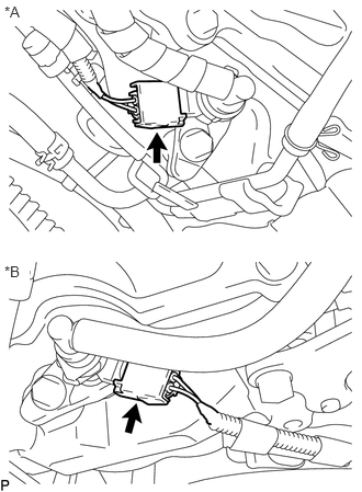
Disconnect the 2 exhaust fuel addition injector connectors.
| *A | for Bank 1 |
| *B | for Bank 2 |
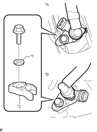
Remove the 2 bolts, 2 washers and 2 nozzle holder clamps.
| *A | for Bank 1 |
| *B | for Bank 2 |
| *1 | Washer |
| *2 | Nozzle Holder Clamp |
Remove the 2 exhaust fuel addition injectors and 2 gaskets.
23901H
37.DISCONNECT FUEL TUBE SUB-ASSEMBLY
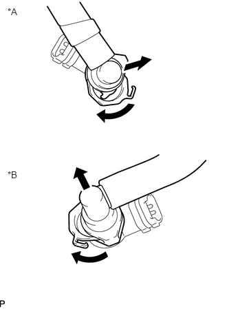
Turn the 2 retainers shown in the illustration.
| *A | for Bank 1 |
| *B | for Bank 2 |
- NOTICE:
- ·
Check for foreign matter on the fuel tube around the fuel tube connector. Clean it if necessary. Foreign matter can affect the ability of the O-ring to seal the fuel tube connector and fuel pipe.
·Do not use any tools to separate the fuel tube connector and fuel pipe.
·Do not forcefully bend, kink or twist the nylon tube.
·Keep the fuel tube connector and fuel pipe free from foreign matter.
·Put the fuel tube connector and fuel pipe in plastic bags to prevent damage and contamination.
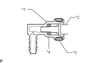
Disconnect the 2 fuel tube connectors from the exhaust fuel addition injector.
| *1 | Fuel Tube Connector |
| *2 | Exhaust Fuel Addition Injector |
| *3 | Retainer |
| *4 | O-Ring |
23255B
38.REMOVE FUEL INJECTOR SEAL
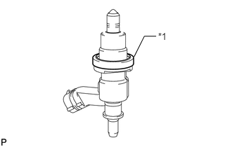
Remove the 2 fuel injector seals.
| *1 | Fuel Injector Seal |