1UR-FE INTAKE / EXHAUST INTAKE MANIFOLD REMOVAL
PROCEDURE

 1. DISCHARGE FUEL SYSTEM PRESSURE
2. PRECAUTION
- NOTICE:
-
After turning the engine switch off, waiting time may be required before disconnecting the cable from the battery terminal. Therefore, make sure to read the disconnecting the cable from the battery terminal notice before proceeding with work (See page General>INTRODUCTION>REPAIR INSTRUCTION>PRECAUTION).
3.DISCONNECT CABLE FROM NEGATIVE BATTERY TERMINAL
- NOTICE:
-
When disconnecting the cable, some systems need to be initialized after the cable is reconnected (See page General>INTRODUCTION>REPAIR INSTRUCTION>INITIALIZATION).
11209
4.REMOVE V-BANK COVER SUB-ASSEMBLY
17705
5.REMOVE AIR CLEANER CAP AND HOSE
53806
6.REMOVE FRONT FENDER SPLASH SHIELD SUB-ASSEMBLY LH
53805
7.REMOVE FRONT FENDER SPLASH SHIELD SUB-ASSEMBLY RH
51405A
8.REMOVE NO. 1 ENGINE UNDER COVER SUB-ASSEMBLY
9.DRAIN ENGINE COOLANT
16289
10.REMOVE NO. 5 WATER BY-PASS PIPE
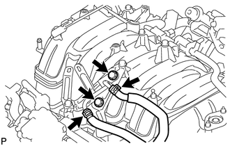
Disconnect the 2 water by-pass hoses and remove the 2 bolts and No. 5 water by-pass pipe.
25625C
11.REMOVE EGR VALVE BRACKET
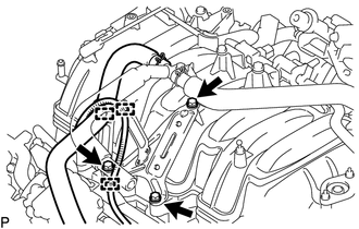
Detach the 2 wire harness clamps and PCV hose clamp.
Remove the 3 bolts and EGR valve bracket.
12263
12.REMOVE PCV HOSE ASSEMBLY
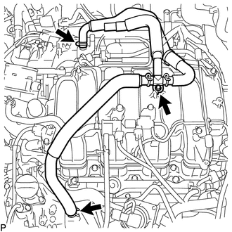
Disconnect the PCV hose from the PCV pipe of the cylinder head cover LH and RH.
Remove the bolt and PCV hose.
13.REMOVE AIR TUBE SUB-ASSEMBLY (w/ Secondary Air Injection System)
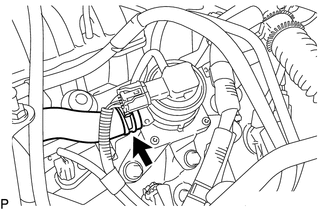
Disconnect the No. 2 air injection system hose from the air switching valve.
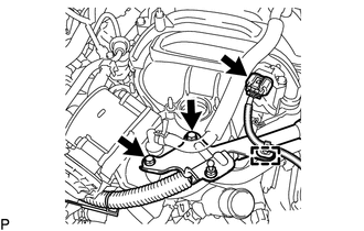
Disconnect the manifold absolute pressure sensor connector and detach the clamp.
Remove the 2 bolts and bracket.
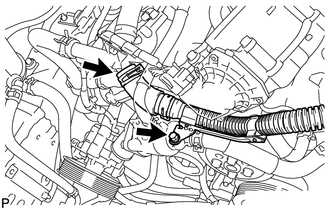
Remove the bolt and air tube.
17111
14.REMOVE INTAKE MANIFOLD
w/o Secondary Air Injection System:
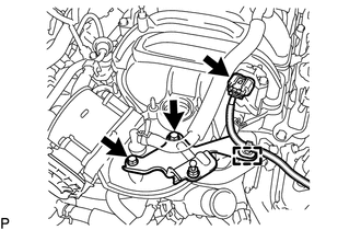
Disconnect the manifold absolute pressure sensor connector and detach the clamp.
Remove the 2 bolts and bracket.
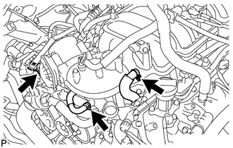
Disconnect the No. 4 water by-pass hose.
Disconnect the throttle position sensor and throttle control motor connector.
Disconnect the PCV valve hose.
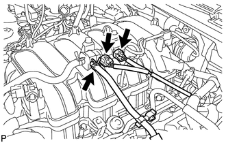
Disconnect the purge VSV connector.
Disconnect the purge line hose from the purge VSV.
Disconnect the vacuum switching valve connector (for ACIS).
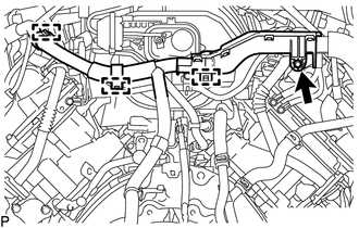
Remove the bolt.
Detach the 3 wire harness clamps from the 3 wire harness brackets.
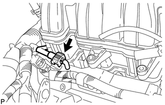
Disconnect the fuel tube from the fuel delivery pipe (See page Engine / Hybrid System>1UR-FE (FUEL)>FUEL SYSTEM>PRECAUTION).
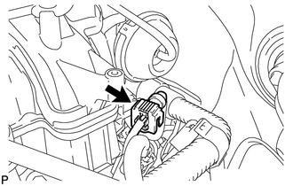
Disconnect the fuel tube from the No. 2 fuel delivery pipe (See page Engine / Hybrid System>1UR-FE (FUEL)>FUEL SYSTEM>PRECAUTION).
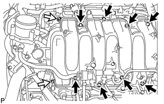
Remove the 2 nuts, 8 bolts, intake manifold and 2 gaskets.

|
Bolt |

|
Nut |
23901
15.REMOVE FUEL TUBE SUB-ASSEMBLY
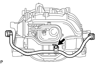
Remove the bolt and fuel tube from the intake manifold.
16.REMOVE BRACKET
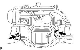
Remove the 2 bolts and 2 brackets.
11254
17.REMOVE V-BANK COVER BRACKET
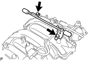
Remove the 2 bolts and V-bank cover bracket.
18.REMOVE V-BANK COVER PIN
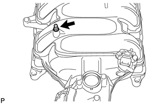
Remove the V-bank cover pin from the intake manifold.
17114A
19.REMOVE INTAKE FLANGE
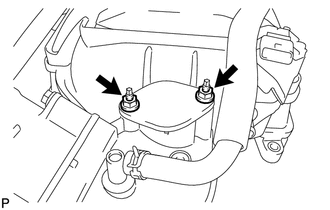
Remove the 2 nuts and intake flange.
20.REMOVE STUD BOLT
- NOTICE:
-
If a stud bolt is deformed or its threads are damaged, replace it.
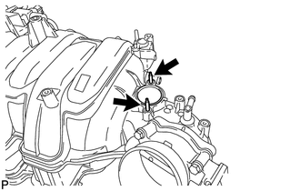
Using an E5 "TORX" socket wrench, remove the 2 stud bolts.
17650
21.REMOVE VACUUM SWITCHING VALVE ASSEMBLY (for ACIS)
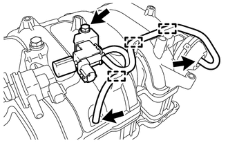
Disconnect the 2 vacuum hoses and detach the 3 clamps.
Remove the bolt and vacuum switching valve.
25860
22.REMOVE PURGE VSV
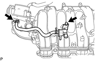
Disconnect the purge line hose from the intake manifold.
Remove the bolt and purge VSV.
89421
23.REMOVE MANIFOLD ABSOLUTE PRESSURE SENSOR
22030
24.REMOVE THROTTLE BODY WITH MOTOR ASSEMBLY
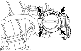
Remove the 4 bolts, throttle body with motor assembly and gasket.