Home › Suspension › SUSPENSION CONTROL › ACTIVE HEIGHT CONTROL SUSPENSION › from 2015.08
RM2660E _53 Suspension _052813 SUSPENSION CONTROL _0255367 ACTIVE HEIGHT CONTROL SUSPENSION C

SUSPENSION CONTROL  ACTIVE HEIGHT CONTROL SUSPENSION  C1731  Front Damping Force Control Actuator RH Circuit Malfunction  C1732  Front Damping Force Control Actuator LH Circuit Malfunction  C1733  Rear Damping Force Control Actuator RH Circuit Malfunction  C1734  Rear Damping Force Control Actuator LH Circuit Malfunction  


DESCRIPTION

The ECU sends a signal to the damping force control actuator to drive the rotary valve of the shock absorber changing the shock absorber damping force.

The actuator is driven electromagnetically by a step motor so that it can accurately follow the driving conditions that change frequently.

DTC Code Detection Condition Trouble Area
C1731 When either of the following is detected:
·

An actuator open-circuit signal is detected for at least 1 second when the actuator operates.

·

An actuator short-circuit signal is consecutively detected 8 times when the actuator operates.


·

Harness or connector

·

Front shock absorber control valve RH (Front damping force control actuator RH)

·

Suspension control ECU


C1732 When either of the following is detected:
·

An actuator open-circuit signal is detected for at least 1 second when the actuator operates.

·

An actuator short-circuit signal is consecutively detected 8 times when the actuator operates.


·

Harness or connector

·

Front shock absorber control valve LH (Front damping force control actuator LH)

·

Suspension control ECU


C1733 When either of the following is detected:
·

An actuator open-circuit signal is detected for at least 1 second when the actuator operates.

·

An actuator short-circuit signal is consecutively detected 8 times when the actuator operates.


·

Harness or connector

·

Rear shock absorber control valve RH (Rear damping force control actuator RH)

·

Suspension control ECU


C1734 When either of the following is detected:
·

An actuator open-circuit signal is detected for at least 1 second when the actuator operates.

·

An actuator short-circuit signal is consecutively detected 8 times when the actuator operates.


·

Harness or connector

·

Rear shock absorber control valve LH (Rear damping force control actuator LH)

·

Suspension control ECU


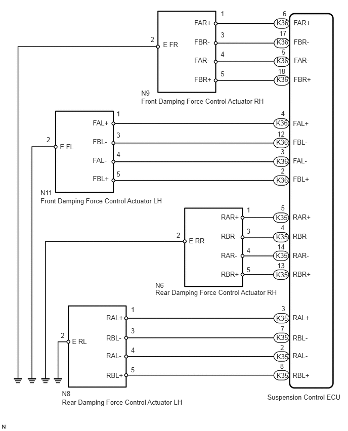
WIRING DIAGRAM

C177526E02
5.697,0.383 5.964,0.532 0.267,0.149 10 K36 5.696,0.783 5.963,0.932 0.267,0.149 10 K36 5.694,1.169 5.961,1.318 0.267,0.149 10 K36 5.694,1.552 5.961,1.701 0.267,0.149 10 K36 5.687,2.849 5.954,2.998 0.267,0.149 10 K36 5.683,2.45 5.950,2.598 0.267,0.149 10 K36 5.691,3.235 5.958,3.384 0.267,0.149 10 K36 5.689,3.621 5.956,3.770 0.267,0.149 10 K36 5.68,4.394 5.947,4.543 0.267,0.149 10 K35 5.685,4.795 5.952,4.944 0.267,0.149 10 K35 5.68,5.18 5.947,5.329 0.267,0.149 10 K35 5.685,5.569 5.952,5.718 0.267,0.149 10 K35 5.687,6.466 5.954,6.615 0.267,0.149 10 K35 5.691,6.869 5.958,7.018 0.267,0.149 10 K35 5.696,7.259 5.963,7.408 0.267,0.149 10 K35 5.696,7.642 5.963,7.791 0.267,0.149 10 K35 5.768,7.462 5.868,7.608 0.099,0.145 10 8 6.026,7.642 6.422,7.831 0.395,0.188 10 RBL+ 6.026,7.238 6.418,7.429 0.392,0.191 10 RAL- 5.773,7.077 5.904,7.214 0.131,0.137 10 2 6.026,6.875 6.377,7.024 0.350,0.149 10 RBL- 5.78,6.688 5.876,6.836 0.096,0.148 10 7 6.026,6.46 6.412,6.652 0.385,0.192 10 RAL+ 5.796,6.275 5.921,6.438 0.125,0.163 10 3 6.029,5.56 6.480,5.772 0.451,0.212 10 RBR+ 5.71,5.385 5.885,5.541 0.174,0.155 10 13 6.029,5.177 6.418,5.330 0.389,0.152 10 RAR- 5.71,4.997 5.886,5.142 0.176,0.145 10 14 6.029,4.784 6.423,4.961 0.394,0.177 10 RBR- 5.78,4.604 5.888,4.745 0.107,0.140 10 4 6.029,4.384 6.438,4.551 0.409,0.167 10 RAR+ 5.786,4.198 5.908,4.358 0.122,0.160 10 5 6.034,3.606 6.465,3.796 0.430,0.190 10 FBL+ 5.784,3.434 5.929,3.587 0.145,0.152 10 2 6.034,3.228 6.364,3.402 0.330,0.174 10 FAL- 5.78,3.039 5.884,3.191 0.104,0.152 10 3 6.034,2.841 6.495,3.039 0.461,0.198 10 FBL- 5.71,2.674 5.886,2.830 0.176,0.156 10 12 6.034,2.454 6.399,2.606 0.364,0.152 10 FAL+ 5.787,2.254 5.895,2.403 0.107,0.149 10 4 6.05,1.55 6.473,1.715 0.423,0.165 10 FBR+ 5.724,1.382 5.915,1.527 0.191,0.145 10 18 6.054,1.161 6.456,1.349 0.402,0.188 10 FAR- 5.801,0.986 5.905,1.142 0.104,0.156 10 5 6.047,0.782 6.510,0.981 0.462,0.199 10 FBR- 5.749,0.602 5.934,0.751 0.185,0.149 10 17 6.046,0.388 6.434,0.534 0.388,0.147 10 FAR+ 5.822,0.2 5.933,0.338 0.111,0.139 10 6 4.001,1.548 4.424,1.712 0.423,0.165 10 FBR+ 4.001,1.159 4.403,1.347 0.402,0.188 10 FAR- 4.001,0.78 4.463,0.979 0.462,0.199 10 FBR- 4.001,0.386 4.389,0.532 0.388,0.147 10 FAR+ 3.358,0.837 3.787,1.035 0.430,0.198 10 E FR 4.544,0.2 4.672,0.363 0.128,0.163 10 1 4.544,0.638 4.663,0.793 0.119,0.156 10 3 4.544,1.034 4.686,1.197 0.142,0.163 10 4 4.544,1.436 4.695,1.600 0.151,0.164 10 5 3.1,0.729 3.210,0.887 0.110,0.158 10 2 2.4,2.259 2.528,2.422 0.128,0.163 10 1 2.4,2.697 2.519,2.853 0.119,0.156 10 3 2.4,3.094 2.542,3.257 0.142,0.163 10 4 2.4,3.496 2.552,3.659 0.151,0.164 10 5 0.957,2.788 1.066,2.946 0.110,0.158 10 2 5.079,4.237 5.207,4.399 0.128,0.163 10 1 5.079,4.674 5.198,4.830 0.119,0.156 10 3 5.079,5.071 5.221,5.234 0.142,0.163 10 4 5.079,5.473 5.230,5.637 0.151,0.164 10 5 3.635,4.765 3.745,4.924 0.110,0.158 10 2 2.696,6.291 2.824,6.454 0.128,0.163 10 1 2.696,6.729 2.814,6.885 0.119,0.156 10 3 2.696,7.126 2.838,7.289 0.142,0.163 10 4 2.696,7.528 2.847,7.691 0.151,0.164 10 5 1.252,6.82 1.361,6.978 0.110,0.158 10 2 1.91,3.595 2.341,3.785 0.430,0.190 10 FBL+ 1.91,3.217 2.240,3.391 0.330,0.174 10 FAL- 1.91,2.83 2.371,3.028 0.461,0.198 10 FBL- 1.91,2.443 2.275,2.595 0.364,0.152 10 FAL+ 1.233,2.933 1.567,3.089 0.334,0.156 10 E FL 4.551,5.56 5.002,5.772 0.451,0.212 10 RBR+ 4.551,5.177 4.940,5.330 0.389,0.152 10 RAR- 4.551,4.784 4.945,4.961 0.394,0.177 10 RBR- 4.551,4.384 4.960,4.551 0.409,0.167 10 RAR+ 3.889,4.87 4.273,5.040 0.384,0.170 10 E RR 2.188,7.642 2.583,7.831 0.395,0.188 10 RBL+ 2.188,7.238 2.580,7.429 0.392,0.191 10 RAL- 2.188,6.875 2.538,7.024 0.350,0.149 10 RBL- 2.188,6.46 2.573,6.652 0.385,0.192 10 RAL+ 1.484,6.943 1.851,7.106 0.367,0.163 10 E RL 2.908,1.833 3.128,1.995 0.220,0.162 10 N9 2.908,2 5.834,2.163 2.926,0.163 10 Front Damping Force Control Actuator RH 0.834,3.883 1.110,4.045 0.276,0.162 10 N11 0.834,4.05 3.659,4.213 2.825,0.163 10 Front Damping Force Control Actuator LH 3.199,5.793 3.427,5.956 0.228,0.163 10 N6 3.199,5.937 5.906,6.114 2.707,0.177 10 Rear Damping Force Control Actuator RH 1.275,8.026 1.496,8.187 0.220,0.162 10 N8 1.275,8.193 4.257,8.355 2.982,0.163 10 Rear Damping Force Control Actuator LH 5.505,8.091 7.106,8.268 1.600,0.177 10 Suspension Control ECU

CAUTION / NOTICE / HINT

NOTICE:
·

Before performing troubleshooting, inspect the connectors of related circuits.

·

If the suspension control ECU or height control sensor is replaced, the vehicle height offset calibration must be performed (See page Suspension>SUSPENSION CONTROL>ACTIVE HEIGHT CONTROL SUSPENSION>INITIALIZATION).


PROCEDURE

1.PERFORM ACTIVE TEST USING INTELLIGENT TESTER (DAMPER STEP)
a.

According to the display on the intelligent tester, perform the Active Test.


b.

Check if the damping force control actuator operates in accordance with the Active Test.

AHC
Tester Display Test Part Control Range Diagnostic Note
Damper Step FR Changes front damper RH step min.: 1 step
max.: 16 step
The Damper Step item of the Data List changes to the step selected in the Active Test.
Damper Step FL Changes front damper LH step min.: 1 step
max.: 16 step
The Damper Step item of the Data List changes to the step selected in the Active Test.
Damper Step RR Changes rear damper RH step min.: 1 step
max.: 16 step
The Damper Step item of the Data List changes to the step selected in the Active Test.
Damper Step RL Changes rear damper LH step min.: 1 step
max.: 16 step
The Damper Step item of the Data List changes to the step selected in the Active Test.

OK:

The damping force control actuator operates.


OK

2.RECONFIRM DTC OUTPUT

NG

3.CHECK HARNESS AND CONNECTOR (DAMPING FORCE CONTROL ACTUATOR - SUSPENSION CONTROL ECU)
2.RECONFIRM DTC OUTPUT

b.

Perform a road test.


c.

Check for DTCs.

Result
Result Proceed to
DTC is output A
DTC is not output B


A

3.CHECK HARNESS AND CONNECTOR (DAMPING FORCE CONTROL ACTUATOR - SUSPENSION CONTROL ECU)

B

3.CHECK HARNESS AND CONNECTOR (DAMPING FORCE CONTROL ACTUATOR - SUSPENSION CONTROL ECU)
a.

Check the front side damping force control actuator.

i.

Disconnect the N9 and/or N11 actuator connector.


ii.

Disconnect the K36 ECU connector.

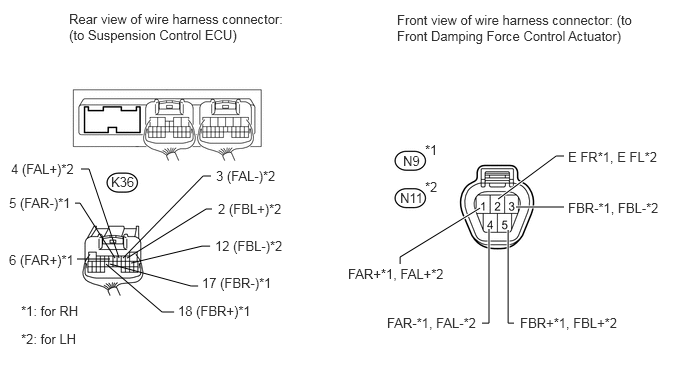
U164789E02
1.146,2.698 0.802,2.698 false 1.365,2.74 2.104,2.563 2.104,2.563 2.188,2.563 false 1.146,2.75 1.99,2.979 1.99,2.979 2.063,2.979 false 1.104,2.75 1.688,3.25 1.688,3.25 1.813,3.25 false 1.323,2.688 2.146,2.177 2.146,2.177 2.208,2.177 false 1.281,2.688 2.115,1.833 2.115,1.833 2.198,1.833 false 0.844,1.76 0.927,1.76 0.927,1.76 1.24,2.688 false 0.781,2.115 0.833,2.115 0.833,2.115 1.198,2.688 false 5.094,2.385 5.094,3.365 5.094,3.365 5.021,3.365 true 5.292,2.396 5.292,3.365 5.292,3.365 5.354,3.365 true 5,2.167 4.167,2.677 4.167,2.677 4.167,2.75 true 5.375,2.156 5.875,2.156 true 5.188,2.073 5.792,1.625 5.792,1.625 5.875,1.625 true 0.719,0.115 3.083,0.469 2.365,0.354 10 false Rear view of wire harness connector: (to Suspension Control ECU) 2.271,2.094 3.167,2.26 0.896,0.167 10 false 2 (FBL+)*2 2.25,1.75 3.104,1.927 0.854,0.177 10 false 3 (FAL-)*2 0.115,1.677 0.844,1.833 0.729,0.156 10 false 4 (FAL+)*2 0.094,2.031 0.792,2.208 0.698,0.177 10 false 5 (FAR-)*1 0.094,2.625 0.823,2.854 0.729,0.229 10 false 6 (FAR+)*1 2.24,2.479 3.063,2.677 0.823,0.198 10 false 12 (FBL-)*2 2.104,2.865 2.99,3.083 0.885,0.219 10 false 17 (FBR-)*1 1.854,3.156 2.677,3.354 0.823,0.198 10 false 18 (FBR+)*1 4.135,0.125 6.604,0.698 2.469,0.573 10 false Front view of wire harness connector: (to Front Damping Force Control Actuator) 0.219,3.448 0.896,3.635 0.677,0.188 10 false *2: for LH 0.219,3.156 0.969,3.344 0.75,0.188 10 false *1: for RH 1.156,1.813 1.469,1.979 0.313,0.167 10 false K36 4.198,1.594 4.49,1.802 0.292,0.208 10 false N9 4.427,1.479 4.604,1.646 0.177,0.167 10 false *1 4.167,1.979 4.49,2.167 0.323,0.188 10 false N11 4.427,1.865 4.604,2.021 0.177,0.156 10 false *2 3.625,2.771 4.719,2.938 1.094,0.167 10 false FAR+*1, FAL+*2 4.031,3.281 5.021,3.469 0.99,0.188 10 false FAR-*1, FAL-*2 5.417,3.281 6.5,3.438 1.083,0.156 10 false FBR+*1, FBL+*2 5.917,2.083 6.938,2.281 1.021,0.198 10 false FBR-*1, FBL-*2 5.917,1.552 6.885,1.729 0.969,0.177 10 false E FR*1, E FL*2


iii.

Measure the resistance according to the value(s) in the table below.

Standard Resistance:
for RH (C1731)
Tester Connection Condition Specified Condition
K36-5 (FAR-) - N9-4 (FAR-) Always Below 1 Ω
K36-5 (FAR-) - Body ground Always 10 kΩ or higher
K36-6 (FAR+) - N9-1 (FAR+) Always Below 1 Ω
K36-6 (FAR+) - Body ground Always 10 kΩ or higher
K36-17 (FBR-) - N9-3 (FBR-) Always Below 1 Ω
K36-17 (FBR-) - Body ground Always 10 kΩ or higher
K36-18 (FBR+) - N9-5 (FBR+) Always Below 1 Ω
K36-18 (FBR+) - Body ground Always 10 kΩ or higher
N9-2 (E FR) - Body ground Always Below 1 Ω

for LH (C1732)
Tester Connection Condition Specified Condition
K36-2 (FBL+) - N11-5 (FBL+) Always Below 1 Ω
K36-2 (FBL+) - Body ground Always 10 kΩ or higher
K36-3 (FAL-) - N11-4 (FAL-) Always Below 1 Ω
K36-3 (FAL-) - Body ground Always 10 kΩ or higher
K36-4 (FAL+) - N11-1 (FAL+) Always Below 1 Ω
K36-4 (FAL+) - Body ground Always 10 kΩ or higher
K36-12 (FBL-) - N11-3 (FBL-) Always Below 1 Ω
K36-12 (FBL-) - Body ground Always 10 kΩ or higher
N11-2 (E FL) - Body ground Always Below 1 Ω


b.

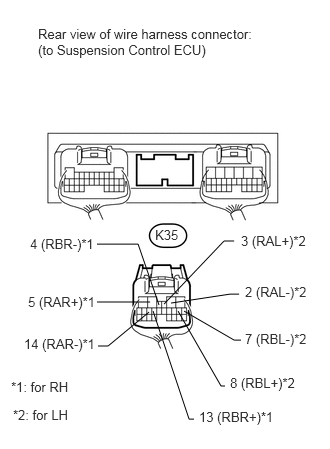
Check the rear side damping force control actuator.

i.

Disconnect the N6 and/or N8 actuator connector.


ii.

Disconnect the K35 ECU connector.

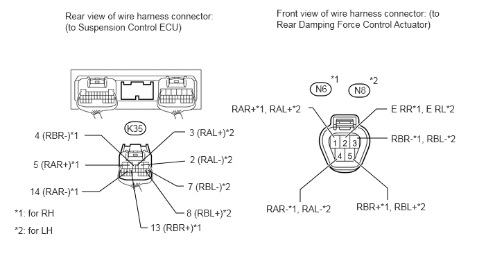
U164790E02
1.948,2.479 1.281,2.479 false 1.927,2.563 1.49,2.875 1.49,2.875 1.229,2.875 false 1.969,2.552 2.115,3.417 2.115,3.417 2.219,3.417 false 2.115,2.479 2.781,2.417 false 2.052,2.49 2.615,1.979 2.615,1.979 2.781,1.979 false 2.01,2.49 1.521,2.031 1.521,2.031 1.271,2.031 false 2.219,2.552 2.656,2.792 2.656,2.792 2.76,2.792 false 2.177,2.552 2.646,3.198 2.646,3.198 2.771,3.198 false 5.021,2.063 4.698,1.615 4.698,1.615 4.635,1.615 true 5.063,2.385 4.51,2.844 4.51,2.844 4.51,3.031 true 5.302,2.385 5.823,2.823 5.823,2.823 5.823,3 true 5.365,2.073 5.823,2.073 false 5.188,2.063 5.656,1.635 5.656,1.635 5.813,1.635 true 0.979,0.156 3.344,0.51 2.365,0.354 10 false Rear view of wire harness connector: (to Suspension Control ECU) 2.802,3.115 3.635,3.281 0.833,0.167 10 false 8 (RBL+)*2 2.854,2.313 3.594,2.49 0.74,0.177 10 false 2 (RAL-)*2 2.844,1.906 3.688,2.063 0.844,0.156 10 false 3 (RAL+)*2 0.521,1.948 1.302,2.125 0.781,0.177 10 false 4 (RBR-)*1 0.5,2.385 1.271,2.615 0.771,0.229 10 false 5 (RAR+)*1 2.823,2.719 3.646,2.917 0.823,0.198 10 false 7 (RBL-)*2 0.448,2.792 1.26,3.01 0.813,0.219 10 false 14 (RAR-)*1 2.26,3.333 3.333,3.531 1.073,0.198 10 false 13 (RBR+)*1 4.156,0.115 6.604,0.615 2.448,0.5 10 false Front view of wire harness connector: (to Rear Damping Force Control Actuator) 0.219,3.115 0.896,3.333 0.677,0.219 10 false *1: for RH 0.219,3.375 0.969,3.667 0.75,0.292 10 false *2: for LH 1.906,1.844 2.208,2.031 0.302,0.188 10 false K35 4.74,1.25 5,1.458 0.26,0.208 10 false N6 4.969,1.104 5.125,1.25 0.156,0.146 10 false *1 5.323,1.271 5.542,1.458 0.219,0.188 10 false N8 5.552,1.125 5.708,1.271 0.156,0.146 10 false *2 3.479,1.552 4.646,1.708 1.167,0.156 10 false RAR+*1, RAL+*2 4,3.052 5.073,3.24 1.073,0.188 10 false RAR-*1, RAL-*2 5.354,3.021 6.479,3.208 1.125,0.188 10 false RBR+*1, RBL+*2 5.875,1.552 6.885,1.719 1.01,0.167 10 false E RR*1, E RL*2 5.875,2 6.99,2.198 1.115,0.198 10 false RBR-*1, RBL-*2


iii.

Measure the resistance according to the value(s) in the table below.

Standard Resistance:
for RH (C1733)
Tester Connection Condition Specified Condition
K35-4 (RBR-) - N6-3 (RBR-) Always Below 1 Ω
K35-4 (RBR-) - Body ground Always 10 kΩ or higher
K35-5 (RAR+) - N6-1 (RAR+) Always Below 1 Ω
K35-5 (RAR+) - Body ground Always 10 kΩ or higher
K35-13 (RBR+) - N6-5 (RBR+) Always Below 1 Ω
K35-13 (RBR+) - Body ground Always 10 kΩ or higher
K35-14 (RAR-) - N6-4 (RAR-) Always Below 1 Ω
K35-14 (RAR-) - Body ground Always 10 kΩ or higher
N6-2 (E RR) - Body ground Always Below 1 Ω

for LH (C1734)
Tester Connection Condition Specified Condition
K35-2 (RAL-) - N8-4 (RAL-) Always Below 1 Ω
K35-2 (RAL-) - Body ground Always 10 kΩ or higher
K35-3 (RAL+) - N8-1 (RAL+) Always Below 1 Ω
K35-3 (RAL+) - Body ground Always 10 kΩ or higher
K35-7 (RBL-) - N8-3 (RBL-) Always Below 1 Ω
K35-7 (RBL-) - Body ground Always 10 kΩ or higher
K35-8 (RBL+) - N8-5 (RBL+) Always Below 1 Ω
K35-8 (RBL+) - Body ground Always 10 kΩ or higher
N8-2 (E RL) - Body ground Always Below 1 Ω


OK

4.INSPECT DAMPING FORCE CONTROL ACTUATOR

NG

REPAIR OR REPLACE HARNESS OR CONNECTOR

4.INSPECT DAMPING FORCE CONTROL ACTUATOR
a.

Check the front side damping force control actuator.

i.

Connect the N9 and/or N11 front absorber control actuator connector.
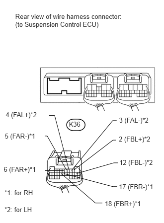

ii.
U164791E01
0.319,0.264 2.684,0.621 2.365,0.357 10 Rear view of wire harness connector: (to Suspension Control ECU) 2.49,2.832 3.237,2.997 0.748,0.165 10 2 (FBL+)*2 2.495,2.437 3.223,2.611 0.728,0.174 10 3 (FAL-)*2 0.117,2.325 0.866,2.485 0.748,0.159 10 4 (FAL+)*2 0.1,2.775 0.814,2.952 0.714,0.177 10 5 (FAR-)*1 0.077,3.471 0.798,3.696 0.721,0.225 10 6 (FAR+)*1 2.501,3.325 3.259,3.518 0.758,0.193 10 12 (FBL-)*2 2.49,3.829 3.257,4.043 0.767,0.214 10 17 (FBR-)*1 2.195,4.184 3.070,4.382 0.876,0.198 10 18 (FBR+)*1 1.337,3.577 0.948,3.577 false 1.604,3.64 2.383,3.415 2.383,3.415 2.471,3.415 false 1.337,3.64 2.368,3.914 2.368,3.914 2.454,3.914 false 1.283,3.64 1.998,4.257 1.998,4.257 2.145,4.257 false 1.547,3.566 2.368,2.938 2.368,2.938 2.428,2.938 false 1.496,3.577 2.362,2.529 2.362,2.529 2.445,2.529 false 1.03,2.423 1.145,2.423 1.145,2.423 1.443,3.562 false 0.939,2.852 0.989,2.852 0.989,2.852 1.391,3.563 false 0.095,3.961 0.860,4.138 0.765,0.177 10 *1: for RH 0.095,4.309 0.806,4.462 0.711,0.152 10 *2: for LH 1.444,2.517 1.710,2.663 0.266,0.145 10 K36

Disconnect the K36 ECU connector.


iii.

Measure the resistance according to the value(s) in the table below.

Standard Resistance:
for RH (C1731)
Tester Connection Condition Specified Condition
K36-5 (FAR-) - Body ground Always 12.0 to 13.6 Ω
K36-6 (FAR+) - Body ground Always 12.0 to 13.6 Ω
K36-17 (FBR-) - Body ground Always 12.0 to 13.6 Ω
K36-18 (FBR+) - Body ground Always 12.0 to 13.6 Ω

for LH (C1732)
Tester Connection Condition Specified Condition
K36-2 (FBL+) - Body ground Always 12.0 to 13.6 Ω
K36-3 (FAL-) - Body ground Always 12.0 to 13.6 Ω
K36-4 (FAL+) - Body ground Always 12.0 to 13.6 Ω
K36-12 (FBL-) - Body ground Always 12.0 to 13.6 Ω


b.

Check the rear side damping force control actuator.

i.

Connect the N6 and/or N8 rear absorber control actuator connector.

ii.
U164796E02
1.563,3.146 1.01,3.146 false 1.552,3.25 1.125,3.604 1.125,3.604 1.021,3.604 false 1.594,3.24 1.969,4.365 1.969,4.365 2.021,4.365 false 1.781,3.156 2.396,3.063 2.396,3.063 2.49,3.063 false 1.708,3.167 2.333,2.51 2.333,2.51 2.438,2.51 false 1.656,3.177 1.438,2.542 1.438,2.542 1.01,2.542 false 1.917,3.24 2.438,3.542 2.438,3.542 2.51,3.542 false 1.854,3.24 2.302,4.021 2.302,4.021 2.344,4.021 false 0.396,0.271 2.76,0.625 2.365,0.354 10 false Rear view of wire harness connector: (to Suspension Control ECU) 2.396,3.906 3.146,4.073 0.75,0.167 10 false 8 (RBL+)*2 2.552,2.958 3.229,3.135 0.677,0.177 10 false 2 (RAL-)*2 2.51,2.427 3.25,2.583 0.74,0.156 10 false 3 (RAL+)*2 0.313,2.458 1.104,2.635 0.792,0.177 10 false 4 (RBR-)*1 0.292,3.063 1.042,3.292 0.75,0.229 10 false 5 (RAR+)*1 2.552,3.448 3.229,3.646 0.677,0.198 10 false 7 (RBL-)*2 0.25,3.5 1.094,3.719 0.844,0.219 10 false 14 (RAR-)*1 2.073,4.26 3,4.458 0.927,0.198 10 false 13 (RBR+)*1 0.115,3.948 0.813,4.156 0.698,0.208 10 false *1: for RH 0.135,4.24 0.823,4.448 0.688,0.208 10 false *2: for LH 1.615,2.365 1.917,2.552 0.302,0.188 10 false K35

Disconnect the K35 ECU connector.


iii.

Measure the resistance according to the value(s) in the table below.

Standard Resistance:
for RH (C1733)
Tester Connection Condition Specified Condition
K35-4 (RBR-) - Body ground Always 12.0 to 13.6 Ω
K35-5 (RAR+) - Body ground Always 12.0 to 13.6 Ω
K35-13 (RBR+) - Body ground Always 12.0 to 13.6 Ω
K35-14 (RAR-) - Body ground Always 12.0 to 13.6 Ω

for LH (C1734)
Tester Connection Condition Specified Condition
K35-2 (RAL-) - Body ground Always 12.0 to 13.6 Ω
K35-3 (RAL+) - Body ground Always 12.0 to 13.6 Ω
K35-7 (RBL-) - Body ground Always 12.0 to 13.6 Ω
K35-8 (RBL+) - Body ground Always 12.0 to 13.6 Ω


Result
Result Proceed to
OK A
Front damping force control actuator RH malfunction B
Front damping force control actuator LH malfunction C
Rear damping force control actuator RH malfunction D
Rear damping force control actuator LH malfunction E


A

REPLACE SUSPENSION CONTROL ECU

B

REPLACE FRONT SHOCK ABSORBER CONTROL VALVE RH

C

REPLACE FRONT SHOCK ABSORBER CONTROL VALVE LH

D

REPLACE REAR SHOCK ABSORBER CONTROL VALVE RH

E

REPLACE REAR SHOCK ABSORBER CONTROL VALVE LH