REAR SUSPENSION REAR COIL SPRING INSTALLATION
CAUTION / NOTICE / HINT
- HINT:
- ·
Use the same procedures for the RH side and LH side.
·The procedures listed below are for the LH side.
·A bolt without a torque specification is shown in the standard bolt chart (See page General>SPECIFICATIONS>STANDARD BOLT>SPECIFIED TORQUE FOR STANDARD BOLTS).
PROCEDURE

 48302
1.INSTALL HOLLOW SPRING SUB-ASSEMBLY
Install the hollow spring to the frame.
48231B
2.INSTALL REAR COIL SPRING LH
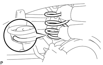
Install the coil spring.
- HINT:
-
Before installing the coil spring, check that the coil spring end is in the correct position. If not, reinstall it.
48540
3.TEMPORARILY INSTALL REAR SHOCK ABSORBER ASSEMBLY LH
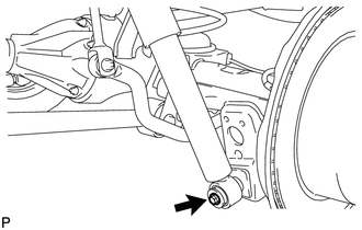
Temporarily install the lower side of the shock absorber with the bolt.
48530
4.TEMPORARILY INSTALL REAR SHOCK ABSORBER ASSEMBLY RH
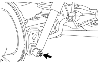
Temporarily install the lower side of the shock absorber with the bolt.
48740
5.TEMPORARILY INSTALL REAR LATERAL CONTROL ROD ASSEMBLY
47318F
6.CONNECT REAR FLEXIBLE HOSE
7.STABILIZE SUSPENSION
48540
8.TIGHTEN REAR SHOCK ABSORBER ASSEMBLY LH
Tighten the bolt.
- Torque:
- 98 N*m (999 kgf*cm, 72 ft.*lbf)
- NOTICE:
-
Perform this procedure with all 4 wheels on the ground.
48530
9.TIGHTEN REAR SHOCK ABSORBER ASSEMBLY RH
Tighten the bolt.
- Torque:
- 98 N*m (999 kgf*cm, 72 ft.*lbf)
- NOTICE:
-
Perform this procedure with all 4 wheels on the ground.
48740
10.TIGHTEN REAR LATERAL CONTROL ROD ASSEMBLY
48825A
11.INSTALL REAR STABILIZER END BRACKET (w/ KDSS)
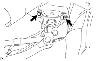
Install the stabilizer end bracket with the 2 bolts.
- Torque:
- 30 N*m (306 kgf*cm, 22 ft.*lbf)
48830
12.CONNECT REAR STABILIZER LINK ASSEMBLY (w/ KDSS)
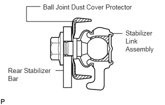
Install the stabilizer link assembly to the ball joint dust cover protector.
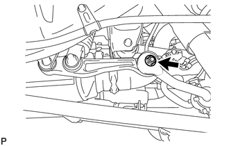
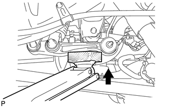
Connect the stabilizer link to the stabilizer bar with the nut.
- Torque:
- 100 N*m (1020 kgf*cm, 74 ft.*lbf)
- HINT:
- ·
If the ball joint turns together with the nut, use a 6 mm hexagon wrench to hold the stud bolt.
·If the rear stabilizer control cylinder extends and it is difficult to temporarily install the stabilizer link to the stabilizer bar, raise the stabilizer control arm with a jack and temporarily install the stabilizer link.
48825A
13.INSTALL REAR STABILIZER END BRACKET LH (w/o KDSS)
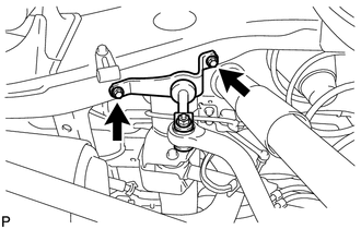
Connect the stabilizer end bracket with the 2 bolts.
- Torque:
- 36 N*m (367 kgf*cm, 27 ft.*lbf)
48825A
14.INSTALL REAR STABILIZER END BRACKET RH (w/o KDSS)
Connect the stabilizer end bracket with the 2 bolts.
- Torque:
- 36 N*m (367 kgf*cm, 27 ft.*lbf)
46430
15.CONNECT NO. 3 PARKING BRAKE CABLE ASSEMBLY
46420
16.CONNECT NO. 2 PARKING BRAKE CABLE ASSEMBLY
42306
17.CONNECT REAR AXLE BREATHER HOSE SUB-ASSEMBLY
18.BLEED BRAKE LINE
19.MEASURE VEHICLE HEIGHT (w/ KDSS)
48860D
20.CLOSE STABILIZER CONTROL WITH ACCUMULATOR HOUSING SHUTTER VALVE (w/ KDSS)
48826D
21.INSTALL STABILIZER CONTROL VALVE PROTECTOR (w/ KDSS)