REAR SUSPENSION REAR SHOCK ABSORBER INSTALLATION
CAUTION / NOTICE / HINT
- HINT:
- ·
Use the same procedures for the RH side and LH side.
·The procedures listed below are for the LH side.
·A bolt without a torque specification is shown in the standard bolt chart (See page General>SPECIFICATIONS>STANDARD BOLT>SPECIFIED TORQUE FOR STANDARD BOLTS).
PROCEDURE

 48540
1.TEMPORARILY INSTALL REAR SHOCK ABSORBER ASSEMBLY LH (w/ Active Height Control)
Install the lower bracket to the shock absorber.
Temporarily install the rear shock absorber and upper bracket with the nut.
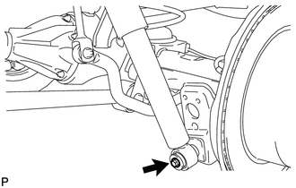
Temporarily install the lower side of the shock absorber with the bolt.
48540
2.TEMPORARILY INSTALL REAR SHOCK ABSORBER ASSEMBLY LH (w/o Active Height Control)
Install the lower bracket to the shock absorber.
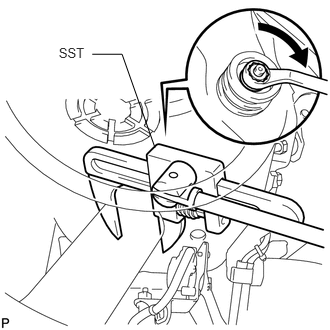
Using SST, hold the rear shock absorber in place.
- SST
- 09922-10010
Temporarily install the rear shock absorber and upper bracket with the nut.
Temporarily install the lower side of the shock absorber with the bolt.
48530
3.TEMPORARILY INSTALL REAR SHOCK ABSORBER ASSEMBLY RH
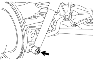
Temporarily install the lower side of the shock absorber with the bolt.
48740
4.TEMPORARILY INSTALL REAR LATERAL CONTROL ROD ASSEMBLY
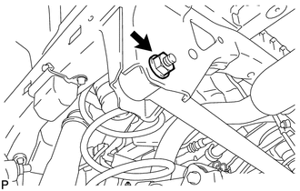
Temporarily install the lateral control rod with the nut and bolt.
5.STABILIZE SUSPENSION
Install the rear wheels.
- Torque:
- for aluminum wheel : 131 N*m (1336 kgf*cm, 97 ft.*lbf)
- for steel wheel : 209 N*m (2131 kgf*cm, 154 ft.*lbf)
Lower the vehicle.
Press down on the vehicle several times to stabilize the suspension.
48540
6.TIGHTEN REAR SHOCK ABSORBER ASSEMBLY LH
w/o Active Height Control:
Tighten the bolt and nut.
- Torque:
- for Nut : 53 N*m (540 kgf*cm, 39 ft.*lbf)
- for Bolt : 98 N*m (999 kgf*cm, 72 ft.*lbf)
w/ Active Height Control:
Tighten the bolt.
- Torque:
- 98 N*m (999 kgf*cm, 72 ft.*lbf)
- NOTICE:
-
Perform this procedure with all 4 wheels on the ground.
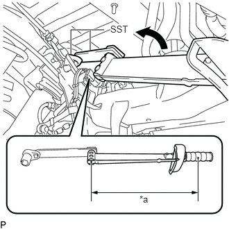
Using SST, Tighten the nut.
- SST
- 09224-00011
09961-01270
- Torque:
- Specified tightening torque : 53 N*m (540 kgf*cm, 39 ft.*lbf)
| *a | Torque Wrench Fulcrum Length |
- NOTICE:
-
Perform this procedure with all 4 wheels on the ground.
- HINT:
- ·
Calculate the torque wrench reading when changing the fulcrum length of the torque wrench (See page General>INTRODUCTION>REPAIR INSTRUCTION>PRECAUTION).
·When using SST (fulcrum length of 30 mm (1.181 in.)) + SST (fulcrum length of 200 mm (7.874 in.)) + torque wrench (fulcrum length of 380 mm (14.961 in.)): 33 N*m (337 kgf*cm, 24 ft.*lbf)
48530
7.TIGHTEN REAR SHOCK ABSORBER ASSEMBLY RH
Tighten the bolt.
- Torque:
- 98 N*m (999 kgf*cm, 72 ft.*lbf)
- NOTICE:
-
Perform this procedure with all 4 wheels on the ground.
49164B
8.CONNECT NO. 4 SUSPENSION CONTROL PRESSURE HOSE (w/ Active Height Control)
Lift the vehicle.
Insert a thin tube into the oil passage at the tip of the rod and inject the suspension fluid.
- HINT:
- ·
Tube:
φ 8 or less
·Suspension Fluid:
Approximately 395 cc
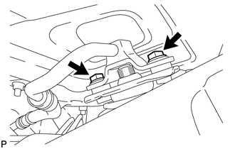
Install the pressure hose with the 2 bolts.
- Torque:
- 18 N*m (184 kgf*cm, 13 ft.*lbf)
Lower the vehicle.
48740
9.TIGHTEN REAR LATERAL CONTROL ROD ASSEMBLY
Tighten the nut.
- Torque:
- 150 N*m (1530 kgf*cm, 111 ft.*lbf)
- NOTICE:
-
Perform this procedure with all 4 wheels on the ground.
10.INSTALL FUEL TANK (w/ Active Height Control)
58321B
11.INSTALL REAR NO. 1 FLOOR HEAT INSULATOR (w/ Active Height Control)
Install the rear No. 1 floor heat insulator with the 3 bolts.
- Torque:
- 5.0 N*m (51 kgf*cm, 44 in.*lbf)
12.INSTALL EXHAUST PIPE ASSEMBLY (w/ Active Height Control)
for 1GR-FE: Engine / Hybrid System>1GR-FE (INTAKE / EXHAUST)>EXHAUST PIPE>INSTALLATION
for 1UR-FE: Engine / Hybrid System>1UR-FE (INTAKE / EXHAUST)>EXHAUST PIPE>INSTALLATION
for 1VD-FTV: Engine / Hybrid System>1VD-FTV (INTAKE / EXHAUST)>EXHAUST PIPE(w/o DPF)>INSTALLATION
for 3UR-FE: Engine / Hybrid System>3UR-FE (INTAKE / EXHAUST)>EXHAUST PIPE>INSTALLATION
13.BLEED AIR FROM SUSPENSION FLUID (w/ Active Height Control)
14.CHECK FLUID LEVEL IN RESERVOIR (w/ Active Height Control)
15.INSPECT FOR SUSPENSION FLUID LEAK (w/ Active Height Control)
46430
16.CONNECT NO. 3 PARKING BRAKE CABLE ASSEMBLY
Connect the No. 3 parking brake cable with the bolt.
- Torque:
- 13 N*m (127 kgf*cm, 9 ft.*lbf)
46420
17.CONNECT NO. 2 PARKING BRAKE CABLE ASSEMBLY
Connect the No. 2 parking brake cable with the bolt.
- Torque:
- 13 N*m (127 kgf*cm, 9 ft.*lbf)
42306
18.CONNECT REAR AXLE BREATHER HOSE SUB-ASSEMBLY
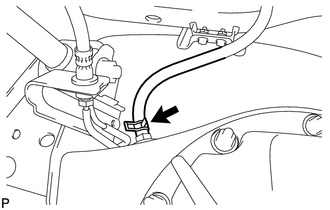
Connect the breather hose to the rear axle housing.
19.MEASURE VEHICLE HEIGHT (w/ KDSS)
48860D
20.CLOSE STABILIZER CONTROL WITH ACCUMULATOR HOUSING SHUTTER VALVE (w/ KDSS)
48826D
21.INSTALL STABILIZER CONTROL VALVE PROTECTOR (w/ KDSS)