BRAKE CONTROL / DYNAMIC CONTROL SYSTEMS VEHICLE STABILITY CONTROL SYSTEM Brake Warning Light Remains ON
DESCRIPTION
The brake warning light comes on when brake fluid is insufficient, the parking brake is applied or the EBD is defective.
WIRING DIAGRAM
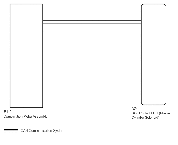
CAUTION / NOTICE / HINT
- NOTICE:
-
After replacing the master cylinder solenoid, perform zero point calibration and store the system information (See page Brake>BRAKE CONTROL / DYNAMIC CONTROL SYSTEMS>VEHICLE STABILITY CONTROL SYSTEM>CALIBRATION).
PROCEDURE
Check for DTCs (See page Brake>BRAKE CONTROL / DYNAMIC CONTROL SYSTEMS>VEHICLE STABILITY CONTROL SYSTEM>DTC CHECK / CLEAR).
| Result | Proceed to |
|---|---|
| DTC is not output | A |
| DTC is output | B |
A
B
OK
NG
A
B
C
D
E
A
B
C
D
E
A
B
C
D
E
OK
NG
OK
NG
Turn the ignition switch off.
Connect the GTS to the DLC3.
Turn the ignition switch ON.
Turn the GTS on.
Enter the following menus: Chassis / ABS/VSC/TRC / Active Test.
| Tester Display | Test Part | Control Range | Diagnostic Note |
|---|---|---|---|
| Brake Warning Light | Brake warning light | Warning light ON/OFF | Observe the combination meter assembly. |
When performing the Brake Warning Light Active Test, check Brake Warning Light in the Data List.
| Tester Display | Measurement Item/Range | Normal Condition | Diagnostic Note |
|---|---|---|---|
| Brake Warning Light | Brake warning light/ ON or OFF | ON: Warning light on
OFF: Warning light off |
- |
| Result | Proceed to | |
|---|---|---|
| Data List Display | Data List Display when Performing Active Test ON/OFF Operation | |
| ON | Changes between ON and OFF | A |
| Does not change between ON and OFF (for LHD) | B | |
| Does not change between ON and OFF (for RHD) | C | |
| OFF | Changes between ON and OFF | A |
| Does not change between ON and OFF (for LHD) | B | |
| Does not change between ON and OFF (for RHD) | C | |
A
B
C