Home › Steering › VARIABLE GEAR RATIO STEERING › VARIABLE GEAR RATIO STEERING SYSTEM › 2014.08–2015.08
RM2660E _55 Steering _052825 VARIABLE GEAR RATIO STEERING _0255448 VARIABLE GEAR RATIO STEERING SYSTEM C

VARIABLE GEAR RATIO STEERING  VARIABLE GEAR RATIO STEERING SYSTEM  C15A3/63  Actuator Malfunction  C15C5/69  Motor Revolution Angle Signal (Test Mode DTC)  


DESCRIPTION

The steering actuator drives the internal motor using the current output from the steering control ECU to change the relative angle between the tire angle and steering wheel angle.

The rotation angle sensor in the steering actuator detects the motor rotation angle and outputs this information to the steering control ECU.

If the steering control ECU detects a malfunction in the rotation angle sensor circuit, it will store DTC C15A3/63.

DTC Code DTC Detection Condition Trouble Area
C15A3/63 The steering control ECU detects a malfunction in the rotation angle sensor circuit.
·

Harness or connector

·

Steering actuator

·

Steering control ECU


C15C5/69 A steering signal indicating a motor rotation angle of 36° or more (to the left or right) is input after entering test mode.*
·

Harness or connector

·

Steering actuator

·

Steering control ECU


HINT:

*: A tire angle of 36° and a motor rotation angle of 36° correspond to the steering wheel angle. The amount of change in tire angle and motor rotation angle is from when the mode is changed to test mode.


WIRING DIAGRAM
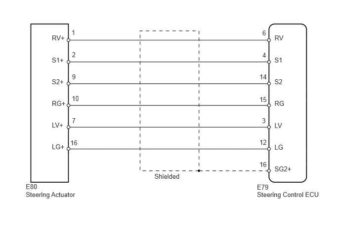
C163901E05
0.543,4.033 1.699,4.216 1.156,0.184 10 Steering Actuator 5.417,4.036 6.816,4.227 1.399,0.191 10 Steering Control ECU 5.417,3.875 5.705,4.045 0.288,0.170 10 E79 3.255,3.641 3.929,3.843 0.673,0.201 10 Shielded 5.786,0.715 6.094,0.899 0.309,0.184 10 RV 5.786,1.189 6.094,1.372 0.309,0.184 10 S1 5.786,1.645 6.094,1.828 0.309,0.184 10 S2 5.786,2.106 6.094,2.290 0.309,0.184 10 RG 5.786,2.568 6.094,2.751 0.309,0.184 10 LV 5.786,3.028 6.094,3.211 0.309,0.184 10 LG 5.786,3.492 6.192,3.676 0.406,0.184 10 SG2+ 1.094,0.715 1.442,0.899 0.348,0.184 10 RV+ 1.094,1.189 1.442,1.372 0.348,0.184 10 S1+ 1.094,1.645 1.442,1.828 0.348,0.184 10 S2+ 1.094,2.106 1.442,2.290 0.348,0.184 10 RG+ 1.094,2.564 1.442,2.747 0.348,0.184 10 LV+ 1.094,3.024 1.442,3.207 0.348,0.184 10 LG+ 5.53,1.082 5.712,1.264 0.182,0.182 10 4 5.53,0.613 5.712,0.796 0.182,0.182 10 6 1.481,2.936 1.691,3.118 0.210,0.182 10 16 1.517,1.076 1.673,1.260 0.156,0.184 10 2 1.508,0.605 1.664,0.789 0.156,0.184 10 1 5.523,2.473 5.679,2.657 0.156,0.184 10 3 1.517,1.543 1.673,1.727 0.156,0.184 10 9 1.517,2.466 1.673,2.650 0.156,0.184 10 7 1.513,2.002 1.723,2.184 0.210,0.182 10 10 5.469,1.537 5.678,1.720 0.210,0.182 10 14 5.469,2.017 5.678,2.199 0.210,0.182 10 15 5.469,2.932 5.678,3.114 0.210,0.182 10 12 5.469,3.396 5.678,3.578 0.210,0.182 10 16 0.543,3.861 0.913,4.028 0.370,0.167 10 E80

PROCEDURE

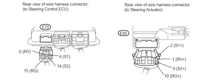
1.CHECK HARNESS AND CONNECTOR (STEERING CONTROL ECU - STEERING ACTUATOR)
U164825E03
1.604,1.854 1.969,1.885 false 1.604,1.906 1.875,2.229 false 1.531,1.854 1.083,1.719 false 1.552,1.906 1.167,2.292 false 5.698,1.542 5.188,2 false 5.25,1.99 5.729,1.99 false 5.25,2.083 5.771,2.281 false 5.188,2.083 5.51,2.521 false 0.76,0.052 3.031,0.469 2.271,0.417 10 false Rear view of wire harness connector: (to Steering Control ECU) 5.792,1.917 6.344,2.115 0.552,0.198 10 false 1 (RV+) 5.729,1.448 6.26,1.646 0.531,0.198 10 false 2 (S1+) 5.531,2.479 6.146,2.625 0.615,0.146 10 false 10 (RG+) 5.813,2.229 6.333,2.396 0.521,0.167 10 false 9 (S2+) 0.646,1.656 1.073,1.854 0.427,0.198 10 false 6 (RV) 1.99,1.823 2.427,2.021 0.438,0.198 10 false 4 (S1) 0.802,2.302 1.344,2.5 0.542,0.198 10 false 15 (RG) 1.917,2.146 2.417,2.344 0.5,0.198 10 false 14 (S2) 1.406,0.833 1.677,1.042 0.271,0.208 10 false E79 4.031,1.042 4.302,1.25 0.271,0.208 10 false E80 4.188,0.073 6.469,0.469 2.281,0.396 10 false Rear view of wire harness connector: (to Steering Actuator)

a.

Disconnect the E79 steering control ECU connector.


b.

Disconnect the E80 steering actuator connector.


c.

Measure the resistance according to the value(s) in the table below.

Standard Resistance:
Tester Connection Condition Specified Condition
E79-4 (S1) - E80-2 (S1+) Always Below 1 Ω
E79-6 (RV) - E80-1 (RV+)
E79-14 (S2) - E80-9 (S2+)
E79-15 (RG) - E80-10 (RG+)
E79-4 (S1) - E79-6 (RV) Always 10 kΩ or higher
E79-4 (S1) - E79-14 (S2)
E79-4 (S1) - E79-15 (RG)
E79-6 (RV) - E79-14 (S2)
E79-6 (RV) - E79-15 (RG)
E79-14 (S2) - E79-15 (RG)
E79-4 (S1) - Body ground
E79-6 (RV) - Body ground
E79-14 (S2) - Body ground
E79-15 (RG) - Body ground


OK

2.CHECK STEERING ACTUATOR

NG

REPAIR OR REPLACE HARNESS OR CONNECTOR

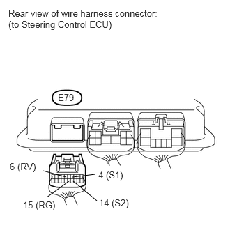
2.CHECK STEERING ACTUATOR
a.
U164531E02
1.417,2.604 1.083,2.646 false 1.083,2.698 1.448,3 false 0.99,2.646 0.646,2.552 false 1.042,2.698 0.698,2.948 false 0.865,1.375 1.125,1.552 0.26,0.177 10 false E79 1.469,2.531 1.917,2.698 0.448,0.167 10 false 4 (S1) 1.479,2.948 1.958,3.115 0.479,0.167 10 false 14 (S2) 0.146,2.406 0.625,2.583 0.479,0.177 10 false 6 (RV) 0.344,2.979 0.885,3.156 0.542,0.177 10 false 15 (RG) 0.125,0.115 2.344,0.51 2.219,0.396 10 false Rear view of wire harness connector: (to Steering Control ECU)

Disconnect the E79 steering control ECU connector.


b.

Measure the resistance according to the value(s) in the table below.

HINT:

The resistance must be measured with the steering actuator connector connected.


Standard Resistance:
Tester Connection Condition Specified Condition
E79-4 (S1) - E79-6 (RV) Always Below 200 Ω
E79-4 (S1) - E79-14 (S2)
E79-4 (S1) - E79-15 (RG)
E79-6 (RV) - E79-14 (S2)
E79-6 (RV) - E79-15 (RG)
E79-14 (S2) - E79-15 (RG)
E79-4 (S1) - Body ground Always 10 kΩ or higher
E79-6 (RV) - Body ground
E79-14 (S2) - Body ground
E79-15 (RG) - Body ground


Result
Result Proceed to
NG A
OK (for LHD) B
OK (for RHD) C


A

REPLACE STEERING ACTUATOR ASSEMBLY

B

C