RM2660E
_55
Steering
_052825
VARIABLE GEAR RATIO STEERING
_0255448
VARIABLE GEAR RATIO STEERING SYSTEM
C
VARIABLE GEAR RATIO STEERING VARIABLE GEAR RATIO STEERING SYSTEM C15A5/65 Actuator Malfunction
DESCRIPTION
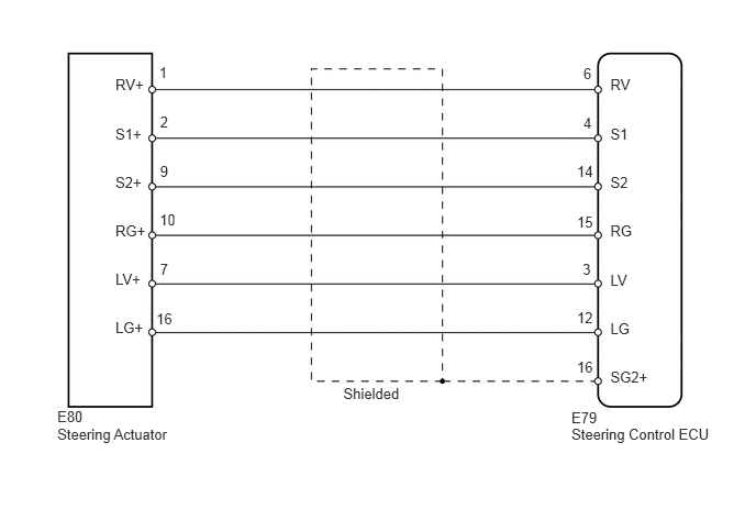
If the steering control ECU detects a malfunction in the lock mechanism, it will turn the master warning light on, store DTC C15A5/65, and stop VGRS operation.
| DTC Code | DTC Detection Condition | Trouble Area |
|---|---|---|
| C15A5/65 | The steering control ECU detects that the LG terminal voltage is abnormal. | ·
Harness or connector ·
Steering actuator ·
Steering control ECU |
WIRING DIAGRAM
0.543,4.033 1.699,4.216
1.156,0.184
10
Steering Actuator
5.417,4.036 6.816,4.227
1.399,0.191
10
Steering Control ECU
5.417,3.875 5.705,4.045
0.288,0.170
10
E79
3.255,3.641 3.929,3.843
0.673,0.201
10
Shielded
5.786,0.715 6.094,0.899
0.309,0.184
10
RV
5.786,1.189 6.094,1.372
0.309,0.184
10
S1
5.786,1.645 6.094,1.828
0.309,0.184
10
S2
5.786,2.106 6.094,2.290
0.309,0.184
10
RG
5.786,2.568 6.094,2.751
0.309,0.184
10
LV
5.786,3.028 6.094,3.211
0.309,0.184
10
LG
5.786,3.492 6.192,3.676
0.406,0.184
10
SG2+
1.094,0.715 1.442,0.899
0.348,0.184
10
RV+
1.094,1.189 1.442,1.372
0.348,0.184
10
S1+
1.094,1.645 1.442,1.828
0.348,0.184
10
S2+
1.094,2.106 1.442,2.290
0.348,0.184
10
RG+
1.094,2.564 1.442,2.747
0.348,0.184
10
LV+
1.094,3.024 1.442,3.207
0.348,0.184
10
LG+
5.53,1.082 5.712,1.264
0.182,0.182
10
4
5.53,0.613 5.712,0.796
0.182,0.182
10
6
1.481,2.936 1.691,3.118
0.210,0.182
10
16
1.517,1.076 1.673,1.260
0.156,0.184
10
2
1.508,0.605 1.664,0.789
0.156,0.184
10
1
5.523,2.473 5.679,2.657
0.156,0.184
10
3
1.517,1.543 1.673,1.727
0.156,0.184
10
9
1.517,2.466 1.673,2.650
0.156,0.184
10
7
1.513,2.002 1.723,2.184
0.210,0.182
10
10
5.469,1.537 5.678,1.720
0.210,0.182
10
14
5.469,2.017 5.678,2.199
0.210,0.182
10
15
5.469,2.932 5.678,3.114
0.210,0.182
10
12
5.469,3.396 5.678,3.578
0.210,0.182
10
16
0.543,3.861 0.913,4.028
0.370,0.167
10
E80
PROCEDURE
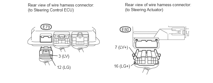
1.CHECK HARNESS AND CONNECTOR (STEERING CONTROL ECU - STEERING ACTUATOR)
1.646,1.854 1.938,1.885
false
1.688,1.906 1.865,2.219
false
4.656,2 4.344,1.594
false
4.406,2.219 4.583,2.094
false
0.938,0.083 3.198,0.5
2.26,0.417
10
false
Rear view of wire harness connector: (to Steering Control ECU)
3.833,2.146 4.417,2.344
0.583,0.198
10
false
16 (LG+)
3.865,1.51 4.344,1.708
0.479,0.198
10
false
7 (LV+)
1.969,1.813 2.385,2.01
0.417,0.198
10
false
3 (LV)
1.917,2.188 2.438,2.385
0.521,0.198
10
false
12 (LG)
1.438,0.823 1.708,1.031
0.271,0.208
10
false
E79
4.094,0.917 4.365,1.125
0.271,0.208
10
false
E80
4.208,0.073 6.427,0.479
2.219,0.406
10
false
Rear view of wire harness connector: (to Steering Actuator)
a.
Disconnect the E79 steering control ECU connector.
b.
Disconnect the E80 steering actuator connector.
c.
Measure the resistance according to the value(s) in the table below.
- Standard Resistance:
Tester Connection Condition Specified Condition E79-3 (LV) - E80-7 (LV+) Always Below 1 Ω E79-12 (LG) - E80-16 (LG+) E79-3 (LV) - Body ground Always 10 kΩ or higher E79-12 (LG) - Body ground
d.
Measure the voltage according to the value(s) in the table below.
- Standard Voltage:
Tester Connection Switch Condition Specified Condition E79-3 (LV) - Body ground Engine switch on (IG) Below 1 V E79-12 (LG) - Body ground
OK
2.CHECK STEERING ACTUATOR (STEERING CONTROL ECU - STEERING ACTUATOR)
NG
REPAIR OR REPLACE HARNESS OR CONNECTOR
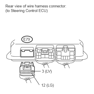
2.CHECK STEERING ACTUATOR (STEERING CONTROL ECU - STEERING ACTUATOR)
a.
Disconnect the E79 steering control ECU connector.
b.
Reconnect the E80 steering actuator connector.
1.49,2.604 1.115,2.604
false
1.438,3.104 1.156,2.677
false
0.198,0.135 2.438,0.583
2.24,0.448
10
false
Rear view of wire harness connector: (to Steering Control ECU)
0.854,1.354 1.115,1.531
0.26,0.177
10
false
E79
1.531,2.521 1.958,2.698
0.427,0.177
10
false
3 (LV)
1.51,3.031 2.031,3.208
0.521,0.177
10
false
12 (LG)
c.
Measure the resistance according to the value(s) in the table below.
- Standard Resistance:
Tester Connection Condition Specified Condition E79-3 (LV) - E79-12 (LG) Always 10 to 100 Ω E79-3 (LV) - Body ground Always 10 kΩ or higher E79-12 (LG) - Body ground
| Result | Proceed to |
|---|---|
| NG | A |
| OK (for LHD) | B |
| OK (for RHD) | C |
A
REPLACE STEERING ACTUATOR ASSEMBLY
B
REPLACE STEERING CONTROL ECU
C
REPLACE STEERING CONTROL ECU