Home › Audio / Visual / Telematics › AUDIO / VIDEO › AUDIO AND VISUAL SYSTEM(w/o Navigation System) › 2014.08–2015.08
RM2660E _56 Audio / Visual / Telematics _052828 AUDIO / VIDEO _0255479 AUDIO AND VISUAL SYSTEM(w/o Navigation System) J

AUDIO / VIDEO  AUDIO AND VISUAL SYSTEM(w/o Navigation System)  Speaker Circuit  


DESCRIPTION

The stereo component amplifier sends sound signals to the speakers.

WIRING DIAGRAM
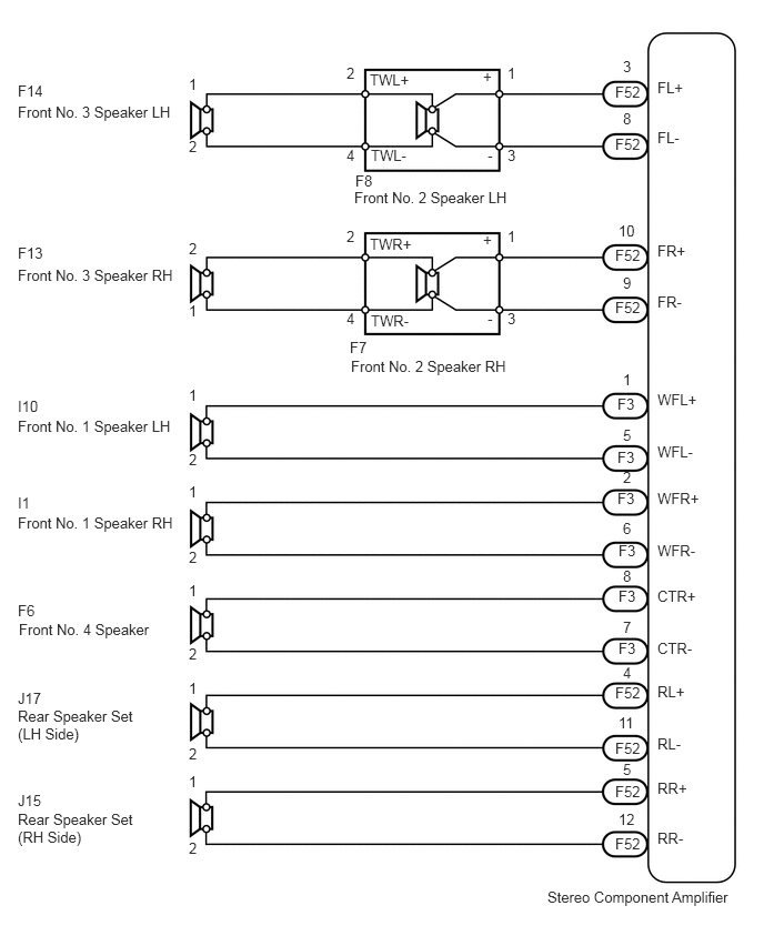
E155742E06
5.135,8.333 6.938,8.521 1.802,0.188 10 false Stereo Component Amplifier 3.323,1.771 4.896,1.958 1.573,0.188 10 false Front No. 2 Speaker LH 3.333,1.615 3.583,1.781 0.25,0.167 10 false F8 3.292,3.354 4.948,3.542 1.656,0.188 10 false Front No. 2 Speaker RH 3.281,3.177 3.531,3.344 0.25,0.167 10 false F7 0.167,0.969 1.656,1.156 1.49,0.188 10 false Front No. 3 Speaker LH 0.167,2.5 1.729,2.688 1.563,0.188 10 false Front No. 3 Speaker RH 1.771,0.708 1.917,0.885 0.146,0.177 10 false 1 1.771,1.292 1.917,1.469 0.146,0.177 10 false 2 1.771,2.25 1.917,2.427 0.146,0.177 10 false 2 1.771,2.833 1.917,3.01 0.146,0.177 10 false 1 0.167,3.917 1.656,4.104 1.49,0.188 10 false Front No. 1 Speaker LH 0.167,4.823 1.708,5.01 1.542,0.188 10 false Front No. 1 Speaker RH 0.177,5.823 1.479,6.01 1.302,0.188 10 false Front No. 4 Speaker 0.167,6.635 1.354,7.052 1.188,0.417 10 false Rear Speaker Set (LH Side) 0.167,7.604 1.385,8.073 1.219,0.469 10 false Rear Speaker Set (RH Side) 1.771,3.625 1.917,3.802 0.146,0.177 10 false 1 1.771,4.229 1.917,4.406 0.146,0.177 10 false 2 1.771,4.531 1.917,4.708 0.146,0.177 10 false 1 1.771,5.146 1.917,5.323 0.146,0.177 10 false 2 1.771,5.458 1.917,5.635 0.146,0.177 10 false 1 1.771,6.052 1.917,6.229 0.146,0.177 10 false 2 1.771,6.375 1.917,6.552 0.146,0.177 10 false 1 1.771,6.99 1.917,7.167 0.146,0.177 10 false 2 1.771,7.25 1.917,7.427 0.146,0.177 10 false 1 1.771,7.875 1.917,8.052 0.146,0.177 10 false 2 4.76,0.604 4.906,0.781 0.146,0.177 10 false 1 3.25,0.604 3.396,0.781 0.146,0.177 10 false 2 4.76,1.375 4.938,1.552 0.177,0.177 10 false 3 6.167,2.271 6.5,2.458 0.333,0.188 10 false FR+ 3.469,0.667 3.927,0.854 0.458,0.188 10 false TWL+ 3.479,1.375 3.885,1.563 0.406,0.188 10 false TWL- 3.25,1.375 3.427,1.552 0.177,0.177 10 false 4 4.531,0.635 4.656,0.813 0.125,0.177 10 false + 4.573,1.375 4.719,1.552 0.146,0.177 10 false - 4.76,2.135 4.906,2.313 0.146,0.177 10 false 1 3.25,2.135 3.396,2.313 0.146,0.177 10 false 2 4.76,2.906 4.938,3.083 0.177,0.177 10 false 3 3.469,2.208 3.927,2.396 0.458,0.188 10 false TWR+ 3.479,2.927 3.885,3.115 0.406,0.188 10 false TWR- 3.25,2.906 3.427,3.083 0.177,0.177 10 false 4 4.531,2.167 4.656,2.344 0.125,0.177 10 false + 4.573,2.906 4.719,3.083 0.146,0.177 10 false - 5.771,0.781 6.031,0.938 0.26,0.156 10 false F52 6.167,2.75 6.5,2.938 0.333,0.188 10 false FR- 6.167,0.74 6.5,0.927 0.333,0.188 10 false FL+ 6.167,1.208 6.5,1.396 0.333,0.188 10 false FL- 5.844,0.542 6.031,0.719 0.188,0.177 10 false 3 5.771,1.271 6.031,1.427 0.26,0.156 10 false F52 5.844,1.031 6.031,1.208 0.188,0.177 10 false 8 5.771,2.313 6.031,2.469 0.26,0.156 10 false F52 5.802,2.083 5.99,2.26 0.188,0.177 10 false 10 5.771,2.802 6.031,2.958 0.26,0.156 10 false F52 5.844,2.573 6.031,2.75 0.188,0.177 10 false 9 5.792,3.708 6.052,3.865 0.26,0.156 10 false F3 5.844,3.479 6.031,3.656 0.188,0.177 10 false 1 5.771,7.833 6.031,7.99 0.26,0.156 10 false F52 5.802,7.604 5.99,7.781 0.188,0.177 10 false 12 5.771,7.344 6.031,7.5 0.26,0.156 10 false F52 5.844,7.135 6.031,7.313 0.188,0.177 10 false 5 5.771,6.938 6.031,7.094 0.26,0.156 10 false F52 5.802,6.698 5.99,6.875 0.188,0.177 10 false 11 5.771,6.417 6.031,6.573 0.26,0.156 10 false F52 5.844,6.229 6.031,6.406 0.188,0.177 10 false 4 5.802,6 6.063,6.156 0.26,0.156 10 false F3 5.844,5.802 6.031,5.979 0.188,0.177 10 false 7 5.802,5.51 6.063,5.667 0.26,0.156 10 false F3 5.844,5.323 6.031,5.5 0.188,0.177 10 false 8 5.802,5.083 6.063,5.24 0.26,0.156 10 false F3 5.844,4.875 6.031,5.052 0.188,0.177 10 false 6 5.792,4.594 6.052,4.75 0.26,0.156 10 false F3 5.844,4.396 6.031,4.573 0.188,0.177 10 false 2 5.792,4.208 6.052,4.365 0.26,0.156 10 false F3 5.844,4 6.031,4.177 0.188,0.177 10 false 5 6.167,3.667 6.583,3.844 0.417,0.177 10 false WFL+ 6.167,4.156 6.583,4.333 0.417,0.177 10 false WFL- 6.167,4.594 6.583,4.771 0.417,0.177 10 false WFR+ 6.167,5.083 6.583,5.26 0.417,0.177 10 false WFR- 6.167,5.51 6.583,5.688 0.417,0.177 10 false CTR+ 6.167,6 6.583,6.177 0.417,0.177 10 false CTR- 6.167,6.406 6.594,6.594 0.427,0.188 10 false RL+ 6.167,6.896 6.615,7.083 0.448,0.188 10 false RL- 6.167,7.313 6.594,7.5 0.427,0.188 10 false RR+ 6.167,7.781 6.625,7.969 0.458,0.188 10 false RR- 0.167,0.771 0.49,0.948 0.323,0.177 10 false F14 0.167,2.292 0.49,2.469 0.323,0.177 10 false F13 0.167,3.729 0.49,3.906 0.323,0.177 10 false I10 0.167,4.635 0.49,4.813 0.323,0.177 10 false I1 0.167,5.646 0.49,5.823 0.323,0.177 10 false F6 0.167,6.469 0.49,6.646 0.323,0.177 10 false J17 0.167,7.427 0.49,7.604 0.323,0.177 10 false J15

PROCEDURE

1.CHECK SPEAKER
a.

Check the malfunctioning speakers.

Result
Result Proceed to
Front No. 4 speaker A
Front No. 2 speaker B
Front No. 1 speaker C
Front No. 3 speaker D
Rear speaker set E


A

2.INSPECT FRONT NO. 4 SPEAKER ASSEMBLY

B

4.INSPECT FRONT NO. 2 SPEAKER ASSEMBLY

C

6.INSPECT FRONT NO. 1 SPEAKER ASSEMBLY

D

8.INSPECT FRONT NO. 3 SPEAKER ASSEMBLY

E

10.INSPECT REAR SPEAKER SET
2.INSPECT FRONT NO. 4 SPEAKER ASSEMBLY
a.
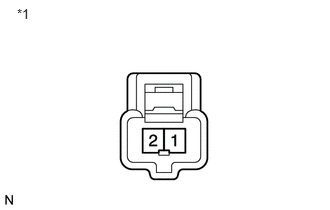
E118525E33
0.177,0.062 0.402,0.274 0.224,0.212 10 *1

Disconnect the F6 speaker connector.


b.

Measure the resistance according to the value(s) in the table below.

Standard Resistance:
Tester Connection Condition Specified Condition
1 - 2 Always 6 Ω


Text in Illustration
*1 Component without harness connected
(Front No. 4 Speaker)


OK

3.CHECK HARNESS AND CONNECTOR (STEREO COMPONENT AMPLIFIER - FRONT NO. 4 SPEAKER)

NG

3.CHECK HARNESS AND CONNECTOR (STEREO COMPONENT AMPLIFIER - FRONT NO. 4 SPEAKER)
a.

Disconnect the F6 speaker connector.


b.

Disconnect the F3 amplifier connector.


c.

Measure the resistance according to the value(s) in the table below.

Standard Resistance:
Tester Connection Condition Specified Condition
F3-8 (CTR+) - F6-1 Always Below 1 Ω
F3-7 (CTR-) - F6-2 Always Below 1 Ω
F3-8 (CTR+) - Body ground Always 10 kΩ or higher
F3-7 (CTR-) - Body ground Always 10 kΩ or higher


OK

REPLACE STEREO COMPONENT AMPLIFIER ASSEMBLY

NG

REPAIR OR REPLACE HARNESS OR CONNECTOR

4.INSPECT FRONT NO. 2 SPEAKER ASSEMBLY
a.
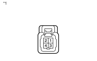
E144969E35
0.114,0.033 0.305,0.220 0.191,0.186 10 *1

Disconnect the F8 and F7 speaker connectors.


b.

Measure the resistance according to the value(s) in the table below.

Standard Resistance:
Tester Connection Condition Specified Condition
1 - 2 Always Below 1 Ω
3 - 4 Always Below 1 Ω
2 - 4 Always 4 Ω


Text in Illustration
*1 Component without harness connected
(Front No. 2 Speaker)


OK

5.CHECK HARNESS AND CONNECTOR (STEREO COMPONENT AMPLIFIER - FRONT NO. 2 SPEAKER)

NG

5.CHECK HARNESS AND CONNECTOR (STEREO COMPONENT AMPLIFIER - FRONT NO. 2 SPEAKER)
a.

Disconnect the F52 amplifier connector.


b.

Disconnect the F8 and F7 speaker connectors.


c.

Measure the resistance according to the value(s) in the table below.

Standard Resistance:
for LH:
Tester Connection Condition Specified Condition
F52-3 (FL+) - F8-1 (+) Always Below 1 Ω
F52-8 (FL-) - F8-3 (-) Always Below 1 Ω
F52-3 (FL+) - Body ground Always 10 kΩ or higher
F52-8 (FL-) - Body ground Always 10 kΩ or higher

for RH:
Tester Connection Condition Specified Condition
F52-10 (FR+) - F7-1 (+) Always Below 1 Ω
F52-9 (FR-) - F7-3 (-) Always Below 1 Ω
F52-10 (FR+) - Body ground Always 10 kΩ or higher
F52-9 (FR-) - Body ground Always 10 kΩ or higher


OK

REPLACE STEREO COMPONENT AMPLIFIER ASSEMBLY

NG

REPAIR OR REPLACE HARNESS OR CONNECTOR

6.INSPECT FRONT NO. 1 SPEAKER ASSEMBLY
a.
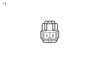
E144966E35
0.163,0.096 0.403,0.280 0.239,0.184 10 *1

Disconnect the I10 and I1 speaker connectors.


b.

Measure the resistance according to the value(s) in the table below.

Standard Resistance:
Tester Connection Condition Specified Condition
1 - 2 Always 3 Ω


Text in Illustration
*1 Component without harness connected
(Front No. 1 Speaker)


OK

7.CHECK HARNESS AND CONNECTOR (STEREO COMPONENT AMPLIFIER - FRONT NO. 1 SPEAKER)

NG

REPLACE FRONT NO. 1 SPEAKER ASSEMBLY

7.CHECK HARNESS AND CONNECTOR (STEREO COMPONENT AMPLIFIER - FRONT NO. 1 SPEAKER)
a.

Disconnect the I10 and I1 speaker connectors.


b.

Disconnect the F3 amplifier connector.


c.

Measure the resistance according to the value(s) in the table below.

Standard Resistance:
for LH:
Tester Connection Condition Specified Condition
F3-1 (WFL+) - I10-1 Always Below 1 Ω
F3-5 (WFL-) - I10-2 Always Below 1 Ω
F3-1 (WFL+) - Body ground Always 10 kΩ or higher
F3-5 (WFL-) - Body ground Always 10 kΩ or higher

for RH:
Tester Connection Condition Specified Condition
F3-2 (WFR+) - I1-1 Always Below 1 Ω
F3-6 (WFR-) - I1-2 Always Below 1 Ω
F3-2 (WFR+) - Body ground Always 10 kΩ or higher
F3-6 (WFR-) - Body ground Always 10 kΩ or higher


OK

REPLACE STEREO COMPONENT AMPLIFIER ASSEMBLY

NG

REPAIR OR REPLACE HARNESS OR CONNECTOR

8.INSPECT FRONT NO. 3 SPEAKER ASSEMBLY
a.
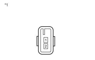
E197034E01
0.091,0.054 0.261,0.215 0.170,0.161 10 *1

Disconnect the F14 and F13 speaker connectors.


b.

Measure the resistance according to the value(s) in the table below.

Standard Resistance:
Tester Connection Condition Specified Condition
1 - 2 Always 4 Ω


Text in Illustration
*1 Component without harness connected
(Front No. 3 Speaker)


OK

9.INSPECT FRONT NO. 2 SPEAKER ASSEMBLY

NG

9.INSPECT FRONT NO. 2 SPEAKER ASSEMBLY
a.
E144969E35
0.114,0.033 0.305,0.220 0.191,0.186 10 *1

Disconnect the F8 and F7 speaker connectors.


b.

Measure the resistance according to the value(s) in the table below.

Standard Resistance:
Tester Connection Condition Specified Condition
1 - 2 Always Below 1 Ω
3 - 4 Always Below 1 Ω
2 - 4 Always 4 Ω


Text in Illustration
*1 Component without harness connected
(Front No. 2 Speaker)


OK

REPAIR OR REPLACE HARNESS OR CONNECTOR (FRONT NO. 2 SPEAKER - FRONT NO. 3 SPEAKER)

NG

10.INSPECT REAR SPEAKER SET
a.
E144966E35
0.163,0.096 0.403,0.280 0.239,0.184 10 *1

Disconnect the J17 and J15 speaker connectors.


b.

Measure the resistance according to the value(s) in the table below.

Standard Resistance:
Tester Connection Condition Specified Condition
1 - 2 Always 4 Ω


Text in Illustration
*1 Component without harness connected
(Rear Speaker Set)


OK

11.CHECK HARNESS AND CONNECTOR (STEREO COMPONENT AMPLIFIER - REAR SPEAKER SET)

NG

11.CHECK HARNESS AND CONNECTOR (STEREO COMPONENT AMPLIFIER - REAR SPEAKER SET)
a.

Disconnect the F52 amplifier connector.


b.

Disconnect the J17 and J15 speaker connectors.


c.

Measure the resistance according to the value(s) in the table below.

Standard Resistance:
for LH:
Tester Connection Condition Specified Condition
F52-4 (RL+) - J17-1 Always Below 1 Ω
F52-11 (RL-) - J17-2 Always Below 1 Ω
F52-4 (RL+) - Body ground Always 10 kΩ or higher
F52-11 (RL-) - Body ground Always 10 kΩ or higher

for RH:
Tester Connection Condition Specified Condition
F52-5 (RR+) - J15-1 Always Below 1 Ω
F52-12 (RR-) - J15-2 Always Below 1 Ω
F52-5 (RR+) - Body ground Always 10 kΩ or higher
F52-12 (RR-) - Body ground Always 10 kΩ or higher


OK

REPLACE STEREO COMPONENT AMPLIFIER ASSEMBLY

NG

REPAIR OR REPLACE HARNESS OR CONNECTOR