Home › Vehicle Interior › METER / GAUGE / DISPLAY › METER / GAUGE SYSTEM › 2014.08–2015.08
RM2660E _58 Vehicle Interior _052841 METER / GAUGE / DISPLAY _0255598 METER / GAUGE SYSTEM J

METER / GAUGE / DISPLAY  METER / GAUGE SYSTEM  Operating Light Control Rheostat does not Change Light Brightness  


DESCRIPTION

w/ Multi-information Display:

When the light control rheostat knob is turned to the left, the combination meter and vehicle interior illumination will become brighter. When the light control rheostat knob is turned to the right, the combination meter and vehicle illumination will dim.

WIRING DIAGRAM
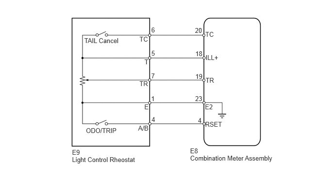
E158833E02
1.809,0.793 2.597,0.942 0.788,0.149 10 TAIL Cancel 1.844,2.726 2.535,2.875 0.691,0.149 10 ODO/TRIP 2.992,0.758 3.211,0.907 0.218,0.149 10 TC 3.1,1.249 3.212,1.398 0.112,0.149 10 T 2.992,1.722 3.211,1.871 0.218,0.149 10 TR 3.097,2.219 3.212,2.368 0.114,0.149 10 E 2.964,2.673 3.211,2.815 0.246,0.142 10 A/B 1.546,3.203 1.743,3.352 0.198,0.149 10 E9 1.546,3.352 2.952,3.501 1.406,0.149 10 Light Control Rheostat 4.08,3.168 4.278,3.324 0.198,0.156 10 E8 4.405,0.66 4.624,0.809 0.218,0.149 10 TC 4.412,1.159 4.714,1.308 0.302,0.149 10 ILL+ 4.41,1.648 4.628,1.797 0.218,0.149 10 TR 4.398,2.217 4.596,2.359 0.198,0.142 10 E2 4.401,2.589 4.793,2.738 0.392,0.149 10 RSET 4.08,3.328 5.930,3.484 1.850,0.156 10 Combination Meter Assembly 3.246,0.565 3.347,0.728 0.100,0.163 10 6 3.251,2.492 3.352,2.655 0.100,0.163 10 4 3.242,2.038 3.343,2.201 0.100,0.163 10 1 3.245,1.548 3.345,1.710 0.100,0.163 10 7 3.248,1.067 3.348,1.230 0.100,0.163 10 5 4.184,0.569 4.361,0.711 0.177,0.142 10 20 4.247,2.509 4.361,2.651 0.114,0.142 10 4 4.188,2.043 4.365,2.185 0.177,0.142 10 23 4.191,1.56 4.368,1.702 0.177,0.142 10 19 4.191,1.076 4.368,1.218 0.177,0.142 10 18

PROCEDURE

1.READ VALUE USING INTELLIGENT TESTER (LIGHT CONTROL RHEOSTAT)
a.

Operate the intelligent tester according to the display and select Data List (See page Vehicle Interior>METER / GAUGE / DISPLAY>METER / GAUGE SYSTEM>DATA LIST / ACTIVE TEST).

Combination Meter
Tester Display Measurement Item/Range Normal Condition Diagnostic Note
Tail Cancel SW* TAIL cancel switch condition/ON or OFF ON: TAIL cancel switch ON
OFF: TAIL cancel switch OFF
-
Rheostat value Light control rheostat switch input/Min.: 0, Max.: 100 Light control rheostat switch is fully turned right (0) → fully turned left (100) Unit: %

HINT:

*: w/ TAIL Cancel Switch


OK:

Light brightness can be changed within specified range by manual operation.


OK

NG

2.INSPECT LIGHT CONTROL RHEOSTAT
a.

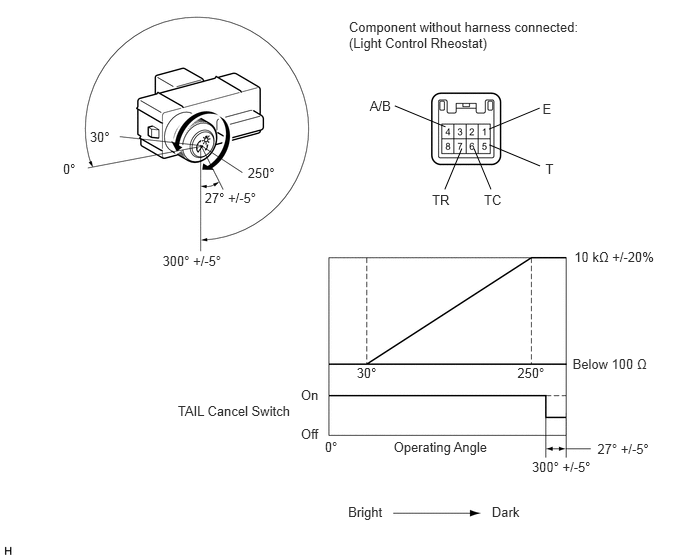
Inspect the light control rheostat.

E154786E04
1.852,4.198 3.116,4.363 1.265,0.165 10 TAIL Cancel Switch 5.041,1.997 5.274,2.167 0.232,0.170 10 TC 5.681,1.674 5.802,1.844 0.121,0.170 10 T 4.5,1.997 4.739,2.167 0.239,0.170 10 TR 5.651,1.055 5.772,1.225 0.121,0.170 10 E 3.851,1.024 4.118,1.194 0.267,0.170 10 A/B 5.093,1.345 5.621,1.125 false 4.64,1.321 4.112,1.102 false 5.625,1.728 5.097,1.508 false 4.937,1.547 5.114,1.972 false 4.81,1.547 4.633,1.972 false 3.634,0.199 6.116,0.549 2.482,0.350 10 Component without harness connected: (Light Control Rheostat) 0.936,1.34 1.254,1.501 0.318,0.161 10 30° 2.58,1.718 2.972,1.879 0.392,0.161 10 250° 1.693,2.634 2.525,2.794 0.832,0.161 10 300° +/-5° 2.132,1.975 2.866,2.136 0.735,0.161 10 27° +/-5° 3.715,3.798 4.033,3.958 0.318,0.161 10 30° 5.541,4.782 6.373,4.942 0.832,0.161 10 300° +/-5° 0.656,1.681 0.900,1.842 0.244,0.161 10 0° 3.384,4.57 3.627,4.731 0.244,0.161 10 0° 3.134,4.03 3.345,4.204 0.211,0.174 10 On 3.134,4.433 3.345,4.607 0.211,0.174 10 Off 6.223,4.595 6.958,4.756 0.735,0.161 10 27° +/-5° 5.964,3.706 6.809,3.866 0.846,0.161 10 Below 100 Ω 5.389,3.798 5.781,3.958 0.392,0.161 10 250° 5.982,2.592 6.895,2.748 0.913,0.156 10 10 kΩ +/-20% 4.1,4.576 5.143,4.742 1.042,0.165 10 Operating Angle 3.626,5.254 4.030,5.419 0.404,0.165 10 Bright 5.123,5.254 5.471,5.419 0.348,0.165 10 Dark

i.

Remove the light control rheostat (See page Vehicle Interior>METER / GAUGE / DISPLAY>LIGHT CONTROL RHEOSTAT>REMOVAL).


ii.

Measure the resistance according to the table below.

Standard Resistance:
Tester Connection Switch Condition Specified Condition
6 (TC) - 1 (E) TAIL cancel switch off → on 10 kΩ or higher → Below 1 Ω
5 (T) - 1 (E) Always 10 kΩ or higher
7 (TR) - 1 (E) Light control rheostat fully turned right → fully turned left 10 kΩ or higher → Below 100 Ω


b.

Inspect the trip switch.

i.

Measure the resistance according to the table below.

Standard Resistance:
Tester Connection Switch Condition Specified Condition
4 (A/B) - 1 (E) TRIP switch on (Pushed) Below 200 Ω
TRIP switch off (Not Pushed) 1 MΩ or higher


OK

3.CHECK HARNESS AND CONNECTOR (COMBINATION METER - LIGHT CONTROL RHEOSTAT)

NG

3.CHECK HARNESS AND CONNECTOR (COMBINATION METER - LIGHT CONTROL RHEOSTAT)
E349720E02
0.927,1.813 1.229,2.042 0.302,0.229 4.594,1.719 4.896,1.948 0.302,0.229 1.396,2.208 1.698,1.896 true 2.625,2.25 2.031,1.906 true 5.354,1.813 5.01,1.521 true 5.99,1.646 5.583,1.813 true 1.677,2.25 1.885,1.906 true 2.26,2.385 1.979,1.906 true 5.958,2.333 5.51,1.938 true 5.438,1.927 5.323,2.417 true 4.938,2.344 5.354,1.938 true 0.885,0.375 3.156,0.813 2.271,0.438 10 false Rear view of wire harness connector: (to Combination Meter Assembly) 0.99,1.844 1.292,2.063 0.302,0.219 10 false E8 1.177,2.229 1.479,2.448 0.302,0.219 10 false E2 2.719,2.24 3.094,2.448 0.375,0.208 10 false ILL+ 4.385,0.354 6.719,0.729 2.333,0.375 10 false Rear view of wire harness connector: (to Light Control Rheostat) 4.813,1.365 5.042,1.583 0.229,0.219 10 false E 6.104,1.531 6.469,1.781 0.365,0.25 10 false A/B 4.656,1.74 4.958,1.958 0.302,0.219 10 false E9 1.5,2.365 1.802,2.583 0.302,0.219 10 false TC 2.365,2.396 2.667,2.615 0.302,0.219 10 false TR 6.021,2.354 6.302,2.594 0.281,0.24 10 false TR 5.208,2.469 5.49,2.708 0.281,0.24 10 false TC 4.813,2.313 5,2.521 0.188,0.208 10 false T

a.

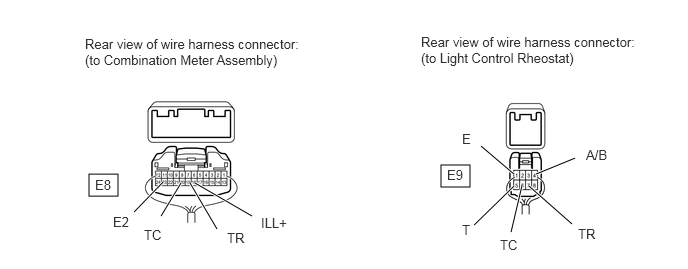
Disconnect the E8 meter connector.


b.

Disconnect the E9 rheostat connector.


c.

Measure the resistance according to the value(s) in the table below.

Standard Resistance:
Tester Connection Condition Specified Condition
E8-18 (ILL+) - E9-5 (T) Always Below 1 Ω
E8-19 (TR) - E9-7 (TR)
E8-23 (E2) - E9-1 (E)
E8-20 (TC) - E9-6 (TC)


OK

NG

REPAIR OR REPLACE HARNESS OR CONNECTOR