Home › Vehicle Interior › SEAT › SEAT HEATER SYSTEM › from 2015.08
RM2660E _58 Vehicle Interior _052845 SEAT _0255627 SEAT HEATER SYSTEM J

SEAT  SEAT HEATER SYSTEM  Seat Heater for Front Right Seat does not Operate  


DESCRIPTION

When the refreshing seat switch is operated, the air conditioning amplifier assembly receives the signal. The air conditioning amplifier assembly receives the signal and operates the front seat heater.

WIRING DIAGRAM
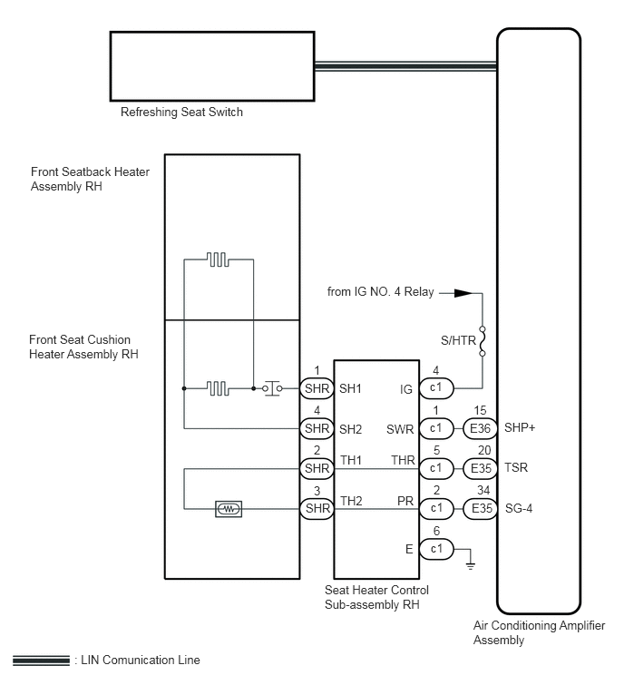
B375837E20
1.385,1.198 3.594,1.448 2.208,0.25 10 false Refreshing Seat Switch 5.438,7.094 7.01,7.573 1.573,0.479 10 false Air Conditioning Amplifier Assembly 5.792,4.823 6.406,5.021 0.615,0.198 10 false SHP+ 5.792,5.281 6.406,5.479 0.615,0.198 10 false TSR 5.802,5.75 6.417,5.948 0.615,0.198 10 false SG-4 5.417,5.75 6.031,5.948 0.615,0.198 10 false E35 5.479,5.542 6.094,5.74 0.615,0.198 10 false 34 5.406,5.292 6.021,5.49 0.615,0.198 10 false E35 5.49,5.083 6.104,5.281 0.615,0.198 10 false 20 5.396,4.833 6.01,5.031 0.615,0.198 10 false E36 5.438,4.625 6.052,4.823 0.615,0.198 10 false 15 4.938,4.354 5.552,4.552 0.615,0.198 10 false c1 4.969,4.167 5.583,4.365 0.615,0.198 10 false 4 4.938,4.823 5.552,5.021 0.615,0.198 10 false c1 4.969,4.625 5.583,4.823 0.615,0.198 10 false 1 4.938,5.281 5.552,5.479 0.615,0.198 10 false c1 4.979,5.083 5.594,5.281 0.615,0.198 10 false 5 4.948,5.74 5.563,5.938 0.615,0.198 10 false c1 4.979,5.542 5.594,5.74 0.615,0.198 10 false 2 3.5,4.375 4.115,4.573 0.615,0.198 10 false SHR 3.604,4.167 4.219,4.365 0.615,0.198 10 false 1 3.5,4.833 4.115,5.031 0.615,0.198 10 false SHR 3.604,4.625 4.219,4.823 0.615,0.198 10 false 4 3.5,5.292 4.115,5.49 0.615,0.198 10 false SHR 3.604,5.083 4.219,5.281 0.615,0.198 10 false 2 3.51,5.75 4.125,5.948 0.615,0.198 10 false SHR 3.604,5.552 4.219,5.75 0.615,0.198 10 false 3 4.948,6.208 5.563,6.406 0.615,0.198 10 false c1 4.979,6.01 5.594,6.208 0.615,0.198 10 false 6 4.594,4.385 5.208,4.583 0.615,0.198 10 false IG 4.438,4.844 5.052,5.042 0.615,0.198 10 false SWR 4.49,5.198 5.104,5.396 0.615,0.198 10 false THR 4.563,5.667 5.177,5.865 0.615,0.198 10 false PR 4.656,6.219 5.271,6.417 0.615,0.198 10 false E 3.896,4.375 4.51,4.573 0.615,0.198 10 false SH1 3.896,4.844 4.51,5.042 0.615,0.198 10 false SH2 3.906,5.198 4.521,5.396 0.615,0.198 10 false TH1 3.906,5.667 4.521,5.865 0.615,0.198 10 false TH2 3.729,6.688 5.021,7.115 1.292,0.427 10 false Seat Heater Control Sub-assembly RH 0.354,1.885 1.802,2.25 1.448,0.365 10 false Front Seatback Heater Assembly RH 0.333,3.813 1.833,4.427 1.5,0.615 10 false Front Seat Cushion Heater Assembly RH 0.854,7.49 3.125,7.688 2.271,0.198 10 false : LIN Comunication Line 5.063,3.823 5.719,4.01 0.656,0.188 10 false S/HTR 3.76,3.26 5.104,3.5 1.344,0.24 10 false from IG NO. 4 Relay

CAUTION / NOTICE / HINT

NOTICE:
·

Inspect the fuses and relays for circuits related to this system before performing the following inspection procedure.

·

First perform the communication function inspections in How to Proceed with Troubleshooting to confirm that there are no LIN communication malfunctions before troubleshooting this symptom.


PROCEDURE

1.CHECK FOR DTC

b.

Check for DTCs (See page Vehicle Interior>SEAT>SEAT HEATER SYSTEM>DTC CHECK / CLEAR).

Result:
Result Proceed to
DTC B14C0 is not output A
DTC B14C0 is output B


A

2.CHECK HARNESS AND CONNECTOR (BATTERY - SEAT HEATER CONTROL SUB-ASSEMBLY RH - BODY GROUND)

B

GO TO DIAGNOSTIC TROUBLE CODE CHART

2.CHECK HARNESS AND CONNECTOR (BATTERY - SEAT HEATER CONTROL SUB-ASSEMBLY RH - BODY GROUND)
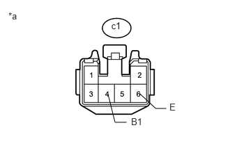
U164310E01
1.661,0.304 1.955,0.460 0.294,0.156 10 c1 0.126,0.161 0.420,0.317 0.294,0.156 10 *a 2.085,1.399 2.327,1.625 2.327,1.625 2.486,1.625 false 1.617,1.424 1.719,1.832 1.719,1.832 1.891,1.832 false 2.532,1.525 2.826,1.680 0.294,0.156 10 E 1.959,1.742 2.253,1.898 0.294,0.156 10 B1

a.

Disconnect the seat heater control sub-assembly RH connector.


b.

Measure the voltage and resistance according to the value(s) in the table below.

Standard Voltage:
Tester Connection Condition Specified Condition
c1-4 (B1) - Body ground Engine switch on (IG) 11 to 14 V
c1-4 (B1) - Body ground Engine switch off (IG) Below 1 V


Standard Resistance:
Tester Connection Condition Specified Condition
c1-6 (E) - Body ground Always Below 1 Ω


Text in Illustration
*a Front view of wire harness connector
(to Seat Heater Control Sub-assembly RH)


OK

3.INSPECT SEAT HEATER CONTROL SUB-ASSEMBLY RH

NG

REPAIR OR REPLACE HARNESS OR CONNECTOR

3.INSPECT SEAT HEATER CONTROL SUB-ASSEMBLY RH
a.

Remove the seat heater control sub-assembly RH (See page Vehicle Interior>SEAT>FRONT SEAT ASSEMBLY (for Power Seat)>DISASSEMBLY).
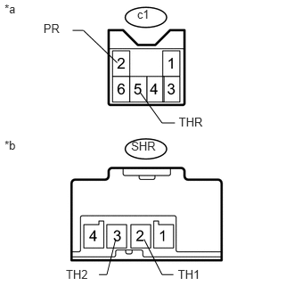

U164353E01
2.08,3.126 2.510,3.292 0.430,0.165 10 TH1 0.77,3.126 1.200,3.292 0.430,0.165 10 TH2 2.09,1.345 2.538,1.552 0.448,0.208 10 THR 0.053,0.017 0.362,0.182 0.310,0.165 10 *a 0.053,1.616 0.362,1.781 0.310,0.165 10 *b 0.508,0.249 0.818,0.414 0.310,0.165 10 PR 2.045,1.437 1.894,1.437 1.894,1.437 1.639,1.082 false 2.027,3.21 1.894,3.21 1.894,3.21 1.684,2.797 false 1.157,3.21 1.249,3.21 1.249,3.21 1.352,2.797 false 0.848,0.355 0.974,0.355 0.974,0.355 1.37,0.733 false 1.602,0.082 1.998,0.287 0.397,0.205 10 c1 1.533,1.62 1.964,1.831 0.431,0.211 10 SHR

b.

Measure the resistance according to the value(s) in the table below.

Standard Resistance:
Tester Connection Condition Specified Condition
c1-5 (THR) - SHL- 2 (TH1) Always Below 1 Ω
c1-5 (THR) or SHL-2 (TH1) - Body ground Always 10k Ω or higher
c1-2 (PR) - SHL-3 (TH2) Always Below 1 Ω
c1-2 (PR) or SHL- 3 (TH2) - Body ground Always 10k Ω or higher


Text in Illustration
*a Seat Heater Control Sub-assembly RH
(to Air Conditioning Amplifier Assembly)
*b Seat Heater Control Sub-assembly RH
(to Front Seat Cushion Heater Assembly RH)


OK

4.INSPECT FRONT SEAT CUSHION HEATER ASSEMBLY RH

NG

REPLACE SEAT HEATER CONTROL SUB-ASSEMBLY RH

4.INSPECT FRONT SEAT CUSHION HEATER ASSEMBLY RH
a.

Remove the front seat cushion heater assembly RH (See page Vehicle Interior>SEAT>FRONT SEAT CUSHION HEATER>REMOVAL).


b.

Inspect the front seat cushion heater assembly RH (See page Vehicle Interior>SEAT>FRONT SEAT CUSHION HEATER>INSPECTION).


OK

5.INSPECT FRONT SEATBACK HEATER ASSEMBLY RH

NG

REPLACE FRONT SEAT CUSHION HEATER ASSEMBLY RH

5.INSPECT FRONT SEATBACK HEATER ASSEMBLY RH
a.

Remove the front seatback heater assembly RH (See page Vehicle Interior>SEAT>FRONT SEATBACK HEATER>REMOVAL).


b.

Inspect the front seatback heater assembly RH (See page Vehicle Interior>SEAT>FRONT SEATBACK HEATER>INSPECTION).


OK

6.CHECK HARNESS AND CONNECTOR (SEAT HEATER CONTROL SUB-ASSEMBLY RH - AIR CONDITIONING AMPLIFIER ASSEMBLY)

NG

REPLACE FRONT SEATBACK HEATER ASSEMBLY RH

6.CHECK HARNESS AND CONNECTOR (SEAT HEATER CONTROL SUB-ASSEMBLY RH - AIR CONDITIONING AMPLIFIER ASSEMBLY)
a.

Disconnect the E35 and E36 air conditioning amplifier assembly connectors.


b.

Disconnect the c1 seat heater control sub-assembly RH connector


c.

Measure the resistance according to the value(s) in the table below.

Standard Resistance:
Tester Connection Condition Specified Condition
E36-15 (SHP+) - c1-1(SWR) Always Below 1 Ω
E36-15 (SHP+) or c1-1 (SWR) - Body ground Always 10 kΩ or higher
E35-20 (TSR) - c1-5 (THR) Always Below 1 Ω
E35-20 (TSR) or c1-5 (THR) - Body ground Always 10 kΩ or higher
E35-34 (SG-4) - c1-2 (PR) Always Below 1 Ω
E35-34 (SG-4) - c1-2 (PR) - Body ground Always 10 kΩ or higher


OK

7.CHECK SEAT HEATER CONTROL SUB-ASSEMBLY RH

NG

REPAIR OR REPLACE HARNESS OR CONNECTOR

7.CHECK SEAT HEATER CONTROL SUB-ASSEMBLY RH
a.

Replace the seat heater control sub-assembly RH (See page Vehicle Interior>SEAT>FRONT SEAT ASSEMBLY (for Power Seat)>DISASSEMBLY).


b.

Check that the front seat heater system is operated normally.

OK:

The front seat heater operates normally.


OK

END (SEAT HEATER CONTROL SUB-ASSEMBLY LH)

NG

8.CHECK AIR CONDITIONING AMPLIFIER ASSEMBLY
a.

Check that the front seat heater (See page Vehicle Interior>SEAT>SEAT HEATER SYSTEM>OPERATION CHECK).


OK

END (AIR CONDITIONING AMPLIFIER ASSEMBLY WAS DEFECTIVE)

NG