INTERIOR PANELS / TRIM ROOF HEADLINING(w/o Sliding Roof) INSTALLATION
CAUTION / NOTICE / HINT
- HINT:
-
A bolt without a torque specification is shown in the standard bolt chart (See page General>SPECIFICATIONS>STANDARD BOLT>SPECIFIED TORQUE FOR STANDARD BOLTS).
PROCEDURE

 62597A
1.INSTALL SIDE TRIM BOX
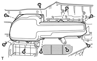
Install the side trim box with the 9 screws.
62598D
2.INSTALL SIDE TRIM BOX COVER
Install the side trim box cover.
62605Q
3.INSTALL QUARTER TRIM LID SUB-ASSEMBLY RH
Install the quarter trim lid.
62522A
4.INSTALL QUARTER TRIM COVER LH (w/o Rear No. 2 Seat or w/ Rear No. 2 Seat, for Face to Face Seat Type)
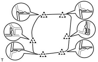
Attach the 6 clips to install the quarter trim cover.
62521B
5.INSTALL QUARTER TRIM COVER RH (w/o Rear No. 2 Seat or w/ Rear No. 2 Seat, for Face to Face Seat Type)
- HINT:
-
Use the same procedures described for the LH side.
71866B
6.INSTALL REAR NO. 2 SEAT COVER BEZEL (w/ Rear No. 2 Seat, except Face to Face Seat Type)
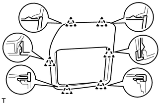
Attach the 6 clips to install the rear No. 2 seat cover bezel.
71865A
7.INSTALL REAR NO. 1 SEAT COVER BEZEL (w/ Rear No. 2 Seat, except Face to Face Seat Type)
- HINT:
-
Use the same procedures described for the rear No. 2 seat cover bezel.
72058C
8.INSTALL REAR SEAT LOCK CONTROL LEVER SUB-ASSEMBLY LH (w/ Rear No. 2 Seat, except Face to Face Seat Type)
72057A
9.INSTALL REAR SEAT LOCK CONTROL LEVER SUB-ASSEMBLY RH (w/ Rear No. 2 Seat, except Face to Face Seat Type)
- HINT:
-
Use the same procedures described for the LH side.
62526D
10.INSTALL NO. 2 SIDE TRIM BASE COVER LH (w/ Rear Heater)
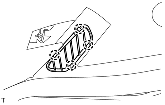
Attach the 4 claws to install the cover.
62516B
11.INSTALL NO. 2 SIDE TRIM BASE COVER RH (w/ Rear Heater)
- HINT:
-
Use the same procedures described for the LH side.
62525D
12.INSTALL NO. 1 SIDE TRIM BASE COVER LH (w/ Rear Heater)
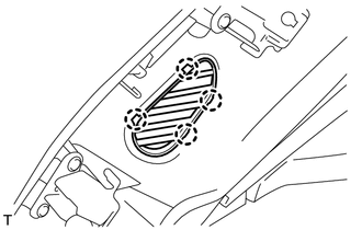
Attach the 4 claws to install the cover.
62515B
13.INSTALL NO. 1 SIDE TRIM BASE COVER RH (w/ Rear Heater)
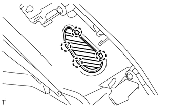
Attach the 4 claws to install the cover.
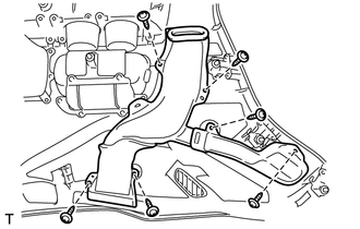
Install the duct with the 6 screws.
64932B
14.INSTALL TONNEAU COVER HANGER LH (w/ Tonneau Cover)
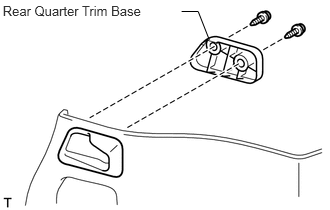
Install the tonneau cover hanger and rear quarter trim base with the 2 screws.
64931B
15.INSTALL TONNEAU COVER HANGER RH (w/ Tonneau Cover)
- HINT:
-
Use the same procedures described for the LH side.
64934A
16.INSTALL TONNEAU COVER HOLDER BRACKET LH (w/ Tonneau Cover)
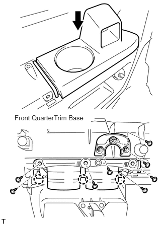
Attach the 3 claws to install the tonneau cover holder bracket.
Install the front quarter trim base with the 3 screws and then install the remaining 5 screws.
64933A
17.INSTALL TONNEAU COVER HOLDER BRACKET RH (w/ Tonneau Cover)
- HINT:
-
Use the same procedures described for the LH side.
66992
18.INSTALL NO. 2 CUP HOLDER
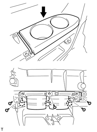
Attach the 3 claws to install the cup holder.
Install the 5 screws.
66991B
19.INSTALL NO. 1 CUP HOLDER
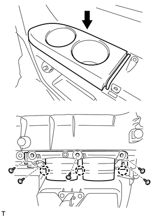
Attach the 3 claws to install the cup holder.
Install the 5 screws.
62502B
20.INSTALL QUARTER TRIM COVER SUB-ASSEMBLY LH
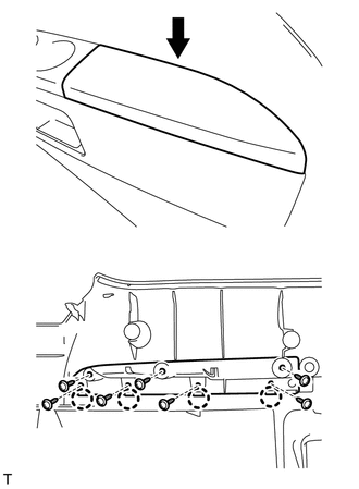
Attach the 4 claws to install the quarter trim cover.
Install the 7 screws.
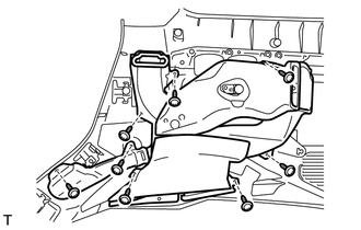
w/ Rear Heater:
Install the duct with the 8 screws.
62501C
21.INSTALL QUARTER TRIM COVER SUB-ASSEMBLY RH
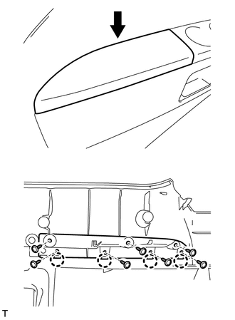
Attach the 4 claws to install the quarter trim cover.
Install the 7 screws.
73372C
22.INSTALL REAR NO. 2 SEAT SHOULDER BELT HANGER LH
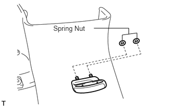
Install the hanger with 2 new spring nuts.
73371C
23.INSTALL REAR NO. 2 SEAT SHOULDER BELT HANGER RH
- HINT:
-
Use the same procedures described for the LH side.
73371A
24.INSTALL REAR SEAT SHOULDER BELT HANGER (w/ Rear No. 2 Seat, except Face to Face Seat Type)
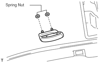
- HINT:
-
Use the same procedure to install the hanger on the other side.
Install the hanger with 2 new spring nuts.
62488A
25.INSTALL ROOF SIDE INNER GARNISH COVER LH (w/ Rear No. 2 Seat, except Face to Face Seat Type)
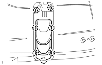
Attach the 7 claws to install the cover.
62487A
26.INSTALL ROOF SIDE INNER GARNISH COVER RH (w/ Rear No. 2 Seat, except Face to Face Seat Type)
- HINT:
-
Use the same procedures described for the LH side.
73034
27.INSTALL REAR SHOULDER BELT ANCHOR PLATE SUB-ASSEMBLY LH
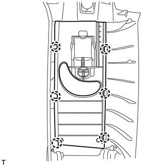
Attach the 6 claws to install the plate.
73033
28.INSTALL REAR SHOULDER BELT ANCHOR PLATE SUB-ASSEMBLY RH
- HINT:
-
Use the same procedures described for the LH side.
73024
29.INSTALL FRONT SHOULDER BELT ANCHOR PLATE SUB-ASSEMBLY LH
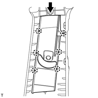
Slide the plate in the direction shown in the illustration and attach the 6 claws to install the plate.
73023
30.INSTALL FRONT SHOULDER BELT ANCHOR PLATE SUB-ASSEMBLY RH
- HINT:
-
Use the same procedures described for the LH side.
67916
31.INSTALL REAR DOOR SCUFF PLATE OUTSIDE LH
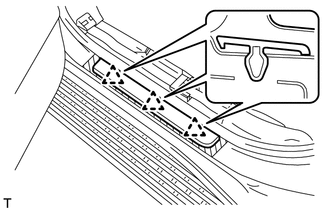
Attach the 3 clips to install the rear door scuff plate outside.
67915
32.INSTALL REAR DOOR SCUFF PLATE OUTSIDE RH
- HINT:
-
Use the same procedures described for the LH side.
67912A
33.INSTALL FRONT DOOR SCUFF PLATE OUTSIDE LH
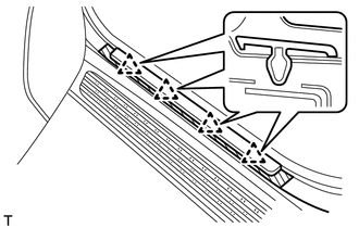
Attach the 4 clips to install the front door scuff plate outside.
67911B
34.INSTALL FRONT DOOR SCUFF PLATE RH
- HINT:
-
Use the same procedures described for the LH side.
67881A
35.INSTALL BACK DOOR WEATHERSTRIP
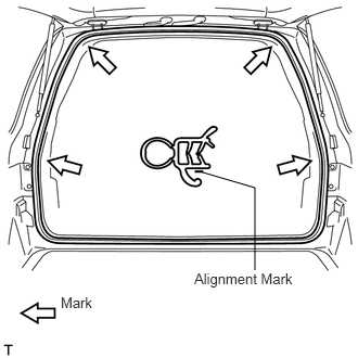
Install the back door weatherstrip as shown in the illustration.
62332A
36.INSTALL REAR DOOR OPENING TRIM WEATHERSTRIP LH
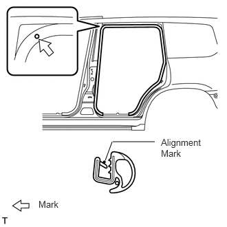
Install the rear door opening trim weatherstrip as shown in the illustration.
62331A
37.INSTALL REAR DOOR OPENING TRIM WEATHERSTRIP RH
- HINT:
-
Use the same procedures described for the LH side.
62312B
38.INSTALL FRONT DOOR OPENING TRIM WEATHERSTRIP LH
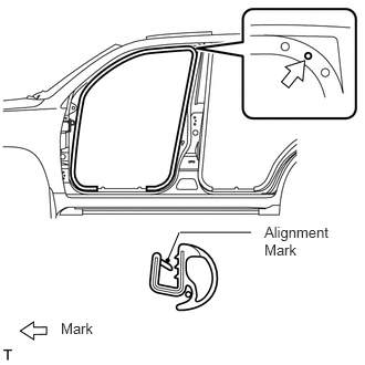
Install the front door opening trim weatherstrip as shown in the illustration.
62311B
39.INSTALL FRONT DOOR OPENING TRIM WEATHERSTRIP RH
- HINT:
-
Use the same procedures described for the LH side.
63310
40.INSTALL ROOF HEADLINING ASSEMBLY
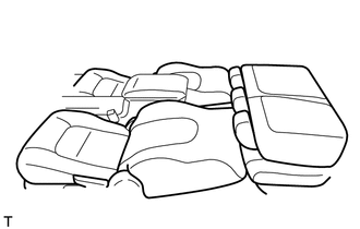
- HINT:
- ·
for Manual Seat:
When installing the roof headlining, move the front seat and rear No. 1 seat to the position shown in the illustration.
·for Power Seat:
When installing the roof headlining, connect the cable to the negative (-) battery terminal and move the front seat and No. 1 rear seat to the position shown in the illustration.
·for Power Seat:
After moving the seats, disconnect the cable from the negative (-) battery terminal.
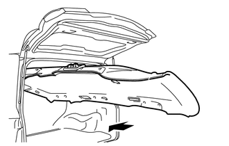
Place the headlining in the cabin from the rear of the vehicle as shown in the illustration.
- NOTICE:
-
Be careful not to damage the roof headlining when placing it in the cabin.
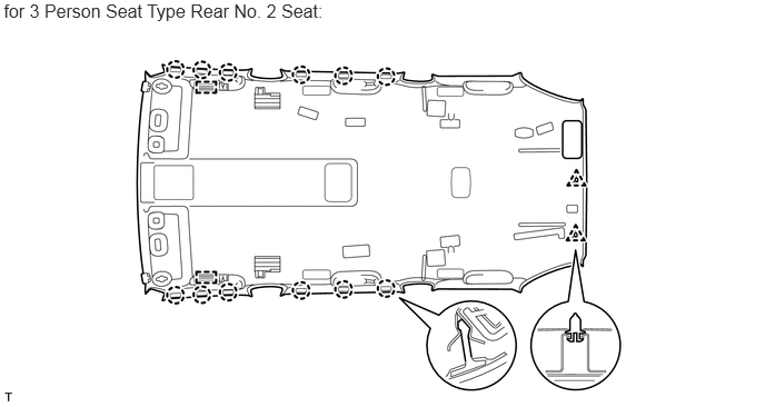
for 3 Person Seat Type Rear No. 2 Seat:
Attach the 2 guides, 12 claws and 2 clips to install the headlining.
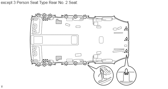
except 3 Person Seat Type Rear No. 2 Seat:
Attach the 2 guides, 12 claws and 3 clips to install the headlining.
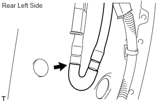
w/ Rear Wiper:
Connect the washer hose.
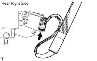
Connect the antenna cord connector.
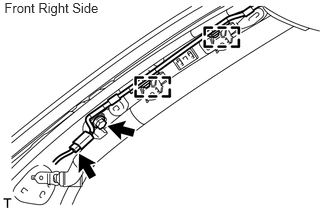
Connect the antenna cord connector and attach the 2 clamps.
Install the bolt.
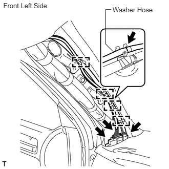
Connect the 3 roof wire connectors and 4 clamps.
w/ Rear Wiper:
Connect the washer hose.
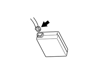
w/ Rain Sensor:
Connect the rain sensor connector.
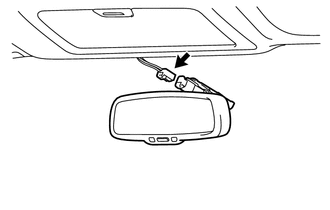
w/ EC Mirror:
Connect the inner mirror connector.
62432C
41.INSTALL FRONT ROOF SIDE RAIL GARNISH LH
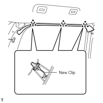
Install 3 new clips to the roof side rail garnish.
Attach the 3 clips to install the roof side rail garnish.
62431C
42.INSTALL FRONT ROOF SIDE RAIL GARNISH RH
- HINT:
-
Use the same procedures described for the LH side.
74630B
43.INSTALL 3RD SEAT ASSIST GRIP ASSEMBLY (w/ Rear No. 2 Seat, except Face to Face Seat Type)
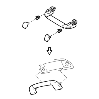
- HINT:
-
Use the same procedure to install the 3rd seat assist grip on the other side.
Assemble the assist grip, 2 clips and 2 covers as shown in the illustration.
Install the assist grip.
74610K
44.INSTALL NO. 2 ASSIST GRIP ASSEMBLY LH
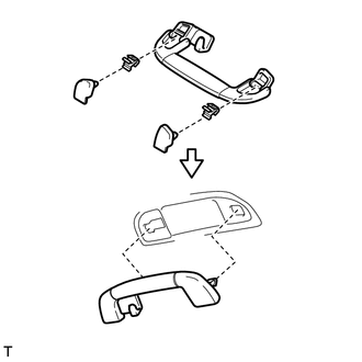
w/ Rear No. 2 Seat, except Face to Face Seat Type or w/o Rear No. 2 Seat:
Install the No. 2 assist grip assembly.
Assemble the assist grip, 2 clips and 2 covers as shown in the illustration.
Install the assist grip.
w/ Rear No. 2 Seat, for Face to Face Seat Type:
Install the No. 2 assist grip assembly.
Assemble the assist grip, 2 clips and 2 covers as shown in the illustration.
Install the assist grip.
74610B
45.INSTALL NO. 2 ASSIST GRIP ASSEMBLY RH
- HINT:
-
Use the same procedures described for the LH side.
74610U
46.INSTALL ASSIST GRIP ASSEMBLY
- HINT:
-
Use the same procedure to install the assist grip on the other side.
Assemble the assist grip, 2 clips and 2 covers as shown in the illustration.
Install the assist grip.
73139B
47.INSTALL SEAT BELT ANCHOR COVER (for 3 Person Seat Type Rear No. 2 Seat)
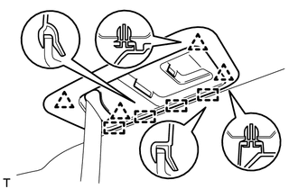
Attach the 4 guides and 4 clips to install the seat belt anchor cover.
89943
48.INSTALL RAIN SENSOR COVER (w/ Rain Sensor)
87834
49.INSTALL INNER REAR VIEW MIRROR STAY HOLDER COVER (w/ EC Mirror)
74330C
50.INSTALL CENTER VISOR ASSEMBLY LH (w/ Sub Visor)
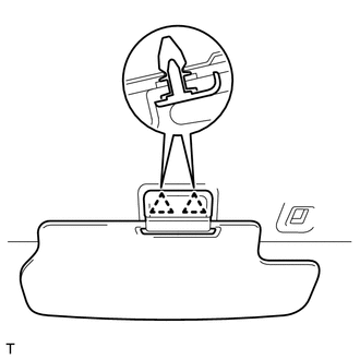
Attach the 2 clips to install the center visor.
74330B
51.INSTALL CENTER VISOR ASSEMBLY RH (w/ Sub Visor)
- HINT:
-
Use the same procedures described for the LH side.
74348
52.INSTALL VISOR HOLDER
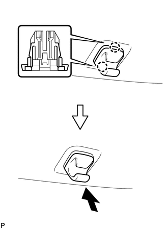
- HINT:
-
Use the same procedures to install the visor holder on the other side.
Attach the 2 claws.
Push the visor holder in to install it.
74320
53.INSTALL VISOR ASSEMBLY LH
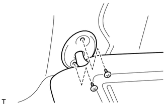
Install the visor with the 2 screws.
74310
54.INSTALL VISOR ASSEMBLY RH
- HINT:
-
Use the same procedures described for the LH side.
74325
55.INSTALL VISOR BRACKET COVER
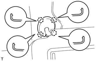
- HINT:
-
Use the same procedure to install the visor bracket cover on the other side.
Attach the 4 claws to install the visor bracket cover.
81240D
56.INSTALL NO. 2 ROOM LIGHT ASSEMBLY
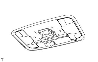
Install the 2 covers.
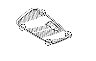
Attach the 4 claws to install the room light lens.
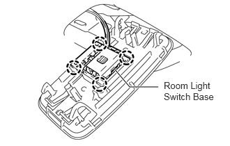
Attach the 4 claws to install the room light to the room light switch base.
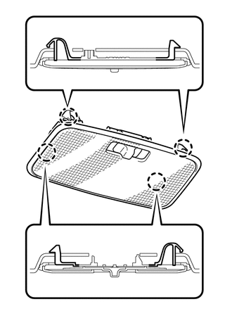
Attach the 4 claws to install the room light.
81240
57.INSTALL NO. 1 ROOM LIGHT ASSEMBLY
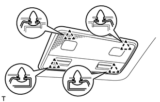
w/ Map Light:
Install the No. 1 room light assembly.
Connect the connector.
Attach the 4 clips to install the room light.
w/o Map Light:
Install the No. 1 room light assembly.
Install the 2 covers.
Attach the 4 claws to install the room light lens.
Attach the 4 claws to install the room light to the room light switch base.
Attach the 4 claws to install the room light.
81260A
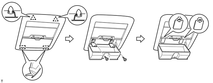
58.INSTALL MAP LIGHT ASSEMBLY (w/ Map Light)
Connect the connector.
Attach the 2 clips and 2 guides to install the map light.
Install the 2 screws.
Attach the 2 claws to close the 2 covers.
62472D
59.INSTALL REAR UPPER PILLAR GARNISH LH
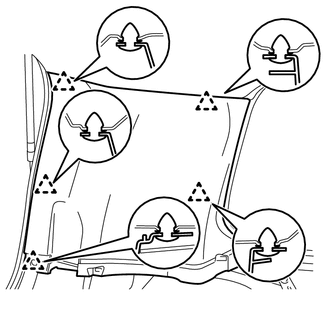
Attach the 5 clips to install the rear upper pillar garnish.
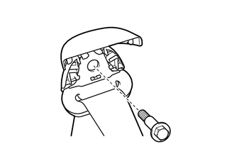
w/ Rear No. 2 Seat, except Face to Face Seat Type:
Install the seat belt shoulder anchor with the bolt.
- Torque:
- 42 N*m (428 kgf*cm, 31 ft.*lbf)
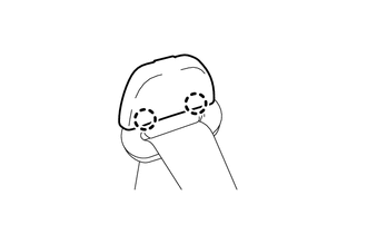
Attach the 2 claws to close the seat belt shoulder anchor cover.
62471D
60.INSTALL REAR UPPER PILLAR GARNISH RH
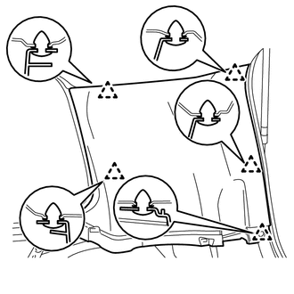
w/o Power Back Door:
Attach the 5 clips to install the rear upper pillar garnish.
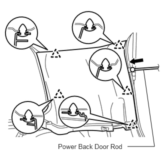
w/ Power Back Door:
Pass the power back door rod through the rear upper pillar garnish.
Attach the 5 clips to install the rear upper pillar garnish.
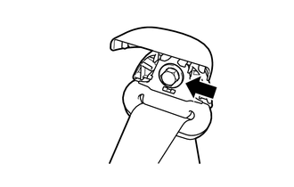
Install the seat belt shoulder anchor with the bolt.
- Torque:
- 42 N*m (428 kgf*cm, 31 ft.*lbf)
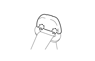
Attach the 2 claws to close the seat belt shoulder anchor cover.
67847
61.INSTALL BACK DOOR SERVICE HOLE COVER RH (w/ Power Back Door)
67937B
62.INSTALL BACK DOOR SIDE GARNISH RH (w/ Power Back Door)
67939B
63.INSTALL CENTER BACK DOOR GARNISH (w/ Power Back Door)
62639
64.INSTALL REAR FRONT QUARTER TRIM GARNISH LH
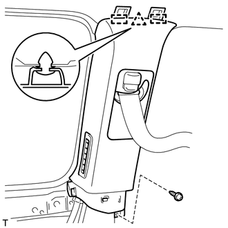
Pass the seat belt anchor through the quarter trim garnish.
Attach the clip and 2 guides to install the quarter trim garnish.
Install the screw.
62638
65.INSTALL REAR FRONT QUARTER TRIM GARNISH RH
- HINT:
-
Use the same procedures described for the LH side.
62520P
66.INSTALL FRONT QUARTER TRIM PANEL ASSEMBLY LH
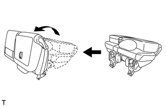
- HINT:
-
When installing the front quarter trim panel, operate the reclining adjuster release handle and move the No. 1 rear seat to the position shown in the illustration.
w/ Rear No. 2 Seat, except Face to Face Seat Type:
w/o Rear Air Conditioning System:
Connect the rear seat lock control lever cable.
w/ Rear Air Conditioning System:
Connect the thermistor connector and rear seat lock control lever cable.
Attach the 18 clips and 2 claws to install the quarter trim panel.
Install the clip and bolt.
- Torque:
- 12 N*m (122 kgf*cm, 9 ft.*lbf)
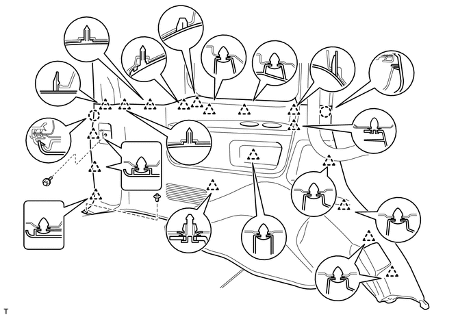
w/o Rear No. 2 Seat or w/ Rear No. 2 Seat, for Face to Face Seat Type:
Attach the 18 clips and 2 claws to install the quarter trim panel.
Install the clip.
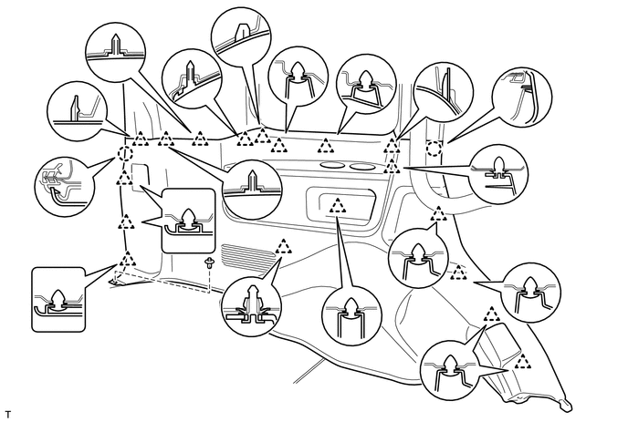
w/ Tonneau Cover:
Attach the 18 clips and 2 claws to install the quarter trim panel.
Install the screw and clip.
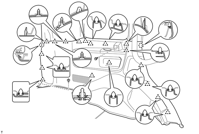
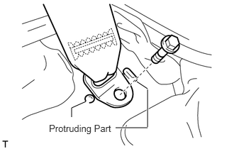
w/ Rear No. 2 Seat, except Face to Face Seat Type:
Install the rear No. 2 seat belt anchor with the bolt.
- Torque:
- 42 N*m (428 kgf*cm, 31 ft.*lbf)
- NOTICE:
-
Do not overlap the anchor part of the seat belt and protruding parts of the vehicle body.
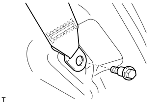
Install the rear No. 1 seat belt anchor with the bolt.
- Torque:
- 42 N*m (428 kgf*cm, 31 ft.*lbf)
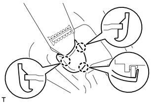
Attach the 3 claws to install the cover.
62510P
67.INSTALL FRONT QUARTER TRIM PANEL ASSEMBLY RH
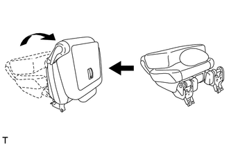
- HINT:
-
When installing the front quarter trim panel, operate the reclining adjuster release handle and move the No. 1 rear seat to the position shown in the illustration.
w/ Rear No. 2 Seat, except Face to Face Seat Type:
w/o Rear Air Conditioning System:
Connect the rear seat lock control lever cable.
w/ Rear Air Conditioning System:
Connect the thermistor connector and rear seat lock control lever cable.
Attach the 16 clips and 2 claws to install the quarter trim panel.
Install the clip and bolt.
- Torque:
- 12 N*m (122 kgf*cm, 9 ft.*lbf)
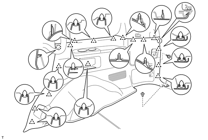
w/o Rear No. 2 Seat or w/ Rear No. 2 Seat, for Face to Face Seat Type:
Attach the 16 clips and 2 claws to install the quarter trim panel.
Install the clip.
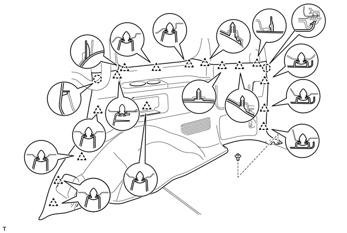
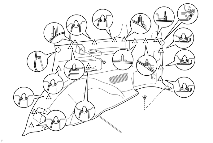
w/ Tonneau Cover:
Attach the 16 clips and 2 claws to install the quarter trim panel.
Install the screw and clip.
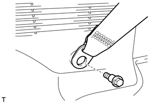
w/ Rear No. 2 Seat, except Face to Face Seat Type:
Install the rear No. 2 seat belt anchor with the bolt.
- Torque:
- 42 N*m (428 kgf*cm, 31 ft.*lbf)
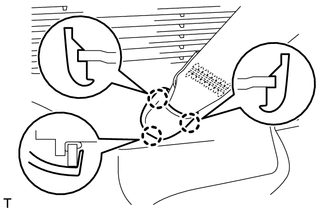
Attach the 3 claws to install the cover.
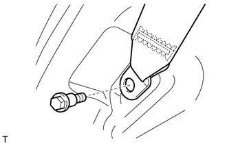
Install the rear No. 1 seat belt anchor with the bolt.
- Torque:
- 42 N*m (428 kgf*cm, 31 ft.*lbf)
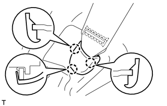
Attach the 3 claws to install the cover.
71845B
68.INSTALL REAR SEAT COVER CAP (w/ Rear No. 2 Seat, except Face to Face Seat Type)
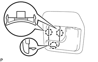
- HINT:
-
Use the same procedure to install the rear seat cover cap on the other side.
Attach the 3 claws to install the rear seat cover cap.
64937A
69.INSTALL NO. 1 TONNEAU COVER HOLDER CAP (w/ Tonneau Cover)
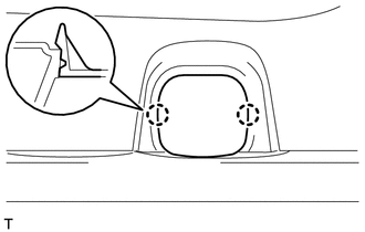
- HINT:
-
Use the same procedure to install the tonneau cover holder cap on the other side.
Attach the 2 claws to install the tonneau cover holder cap.
62412
70.INSTALL CENTER PILLAR GARNISH LH
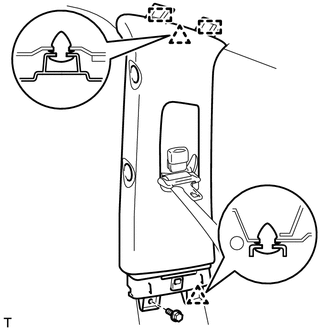
Pass the seat belt anchor through the center pillar garnish.
Attach the 2 clips and 2 guides to install the center pillar garnish.
Install the bolt.
62411
71.INSTALL CENTER PILLAR GARNISH RH
- HINT:
-
Use the same procedures described for the LH side.
74620A
72.INSTALL REAR ASSIST GRIP ASSEMBLY
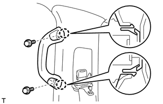
- HINT:
-
Use the same procedure to install the rear assist grip on the other side.
Attach the 2 claws to install the rear assist grip.
Install the 2 bolts.
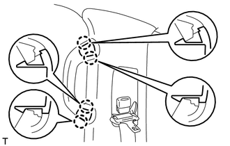
Attach the 4 claws to install the 2 assist grip plugs.
62414A
73.INSTALL CENTER LOWER PILLAR GARNISH LH
- HINT:
- ·
for Manual Seat:
When installing the center lower pillar garnish, move the front seat and seatback to the foremost upright position.
·for Power Seat:
When installing the center lower pillar garnish, connect the cable to the negative (-) battery terminal and operate the power seat switch to move the front seat and seatback to the foremost upright position.
·for Power Seat:
After moving the front seat, disconnect the cable from the negative (-) battery terminal.
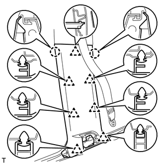
Attach the 2 claws and 7 clips to install the center lower pillar garnish.
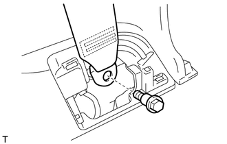
Install the seat belt anchor with the bolt.
- Torque:
- 42 N*m (428 kgf*cm, 31 ft.*lbf)
62413A
74.INSTALL CENTER LOWER PILLAR GARNISH RH
- HINT:
-
Use the same procedures described for the LH side.
62422
75.INSTALL CENTER PILLAR GARNISH COVER LH
- HINT:
- ·
for Manual Seat:
When installing the center pillar garnish cover, move the front seat and seatback to the foremost upright position.
·for Power Seat:
When installing the center pillar garnish cover, connect the cable to the negative (-) battery terminal and operate the power seat switch to move the front seat and seatback to the foremost upright position.
·for Power Seat:
After moving the front seat, disconnect the cable from the negative (-) battery terminal.
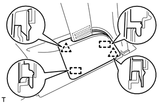
Attach the 2 clips and 2 guides to install the cover.
62421
76.INSTALL CENTER PILLAR GARNISH COVER RH
- HINT:
-
Use the same procedures described for the LH side.
62212
77.INSTALL FRONT PILLAR GARNISH LH
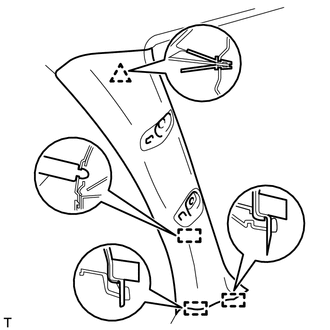
for 9, 14 Speakers:
Connect the speaker connector.
Attach the clip and 3 guides to install the front pillar garnish.
62211
78.INSTALL FRONT PILLAR GARNISH RH
- HINT:
-
Use the same procedures described for the LH side.
74610A
79.INSTALL FRONT ASSIST GRIP SUB-ASSEMBLY
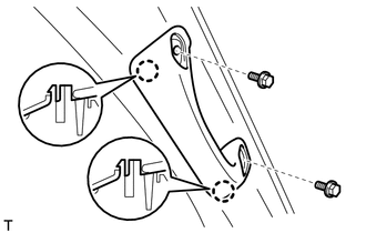
- HINT:
-
Use the same procedure to install the front assist grip on the other side.
Attach the 2 claws to install the front assist grip.
Install the 2 bolts.
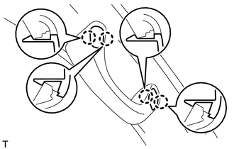
Attach the 4 claws to install the 2 assist grip plugs.
58574A
80.INSTALL REAR FLOOR MAT REAR SUPPORT PLATE
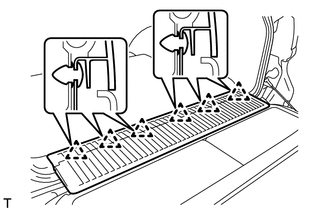
Attach the 6 clips to install the support plate.
67918E
81.INSTALL REAR DOOR SCUFF PLATE LH
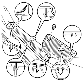
Attach the 3 claws and 4 clips to install the scuff plate.
Install the screw.
67917C
82.INSTALL REAR DOOR SCUFF PLATE RH
- HINT:
-
Use the same procedures described for the LH side.
51775
83.INSTALL REAR STEP COVER
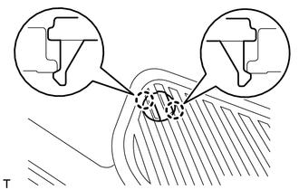
- HINT:
-
Use the same procedure to install the step cover on the other side.
Attach the 2 claws to install the step cover.
67914B
84.INSTALL FRONT DOOR SCUFF PLATE LH
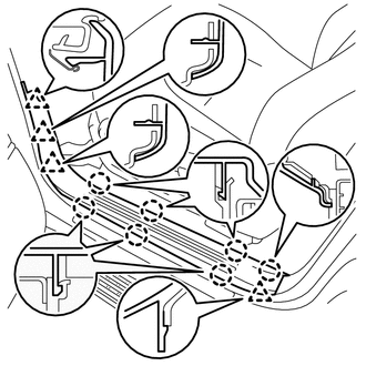
Attach the 7 claws and 4 clips to install the scuff plate.
67913B
85.INSTALL FRONT DOOR SCUFF PLATE RH
- HINT:
-
Use the same procedures described for the LH side.
86.INSTALL REAR NO. 2 SEAT ASSEMBLY LH (except Face to Face Seat Type)
Install the rear No. 2 seat assembly LH (See page Vehicle Interior>SEAT>REAR NO. 2 SEAT ASSEMBLY(except Face to Face Seat Type)>INSTALLATION).
87.INSTALL REAR NO. 2 SEAT ASSEMBLY RH (except Face to Face Seat Type)
- HINT:
-
Use the same procedures described for the LH side.
88.INSTALL REAR NO. 2 SEAT ASSEMBLY LH (for Face to Face Seat Type)
Install the rear No. 2 seat assembly LH (See page Vehicle Interior>SEAT>REAR NO. 2 SEAT ASSEMBLY(for Face to Face Seat Type)>INSTALLATION).
89.INSTALL REAR NO. 2 SEAT ASSEMBLY RH (for Face to Face Seat Type)
- HINT:
-
Use the same procedures described for the LH side.
64910J
90.INSTALL TONNEAU COVER ASSEMBLY (w/ Tonneau Cover)
Install the tonneau cover assembly.
91.CONNECT CABLE TO NEGATIVE BATTERY TERMINAL
- NOTICE:
-
When disconnecting the cable, some systems need to be initialized after the cable is reconnected (See page General>INTRODUCTION>REPAIR INSTRUCTION>INITIALIZATION).