LIGHTING (EXT) LIGHTING SYSTEM Hazard Warning Switch Circuit
DESCRIPTION
The combination meter receives a hazard warning signal switch information signal, and illuminates the turn signal lights.
WIRING DIAGRAM
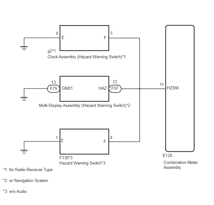
PROCEDURE
Operate the GTS according to the display and select the "Data List".
| Tester Display | Measurement Item/Range | Normal Condition | Diagnostic Note |
|---|---|---|---|
| Hazard Flasher Switch | Hazard switch signal / ON or OFF | ON: Hazard switch on
OFF: Hazard switch off |
- |
OK
NG
Check the vehicle type.
| Result | Proceed to |
|---|---|
| w/ Navigation System | A |
| w/o Audio | B |
| for radio Receiver Type | C |
A
B
C
Remove the multi-display (See page Vehicle Exterior>LIGHTING (EXT)>HAZARD WARNING SWITCH>REMOVAL).
Inspect the multi-display (See page Vehicle Exterior>LIGHTING (EXT)>HAZARD WARNING SWITCH>INSPECTION).
OK
NG
Disconnect the F79 and F97 multi-display connectors.
Disconnect the E120 combination meter connector.
Measure the resistance according to the value(s) in the table below.
- Standard Resistance:
Tester Connection Condition Specified Condition E120-11 (HZSW) - F97-12 (HAZ) Always Below 1 Ω F79-13 (GND1) - Body ground E120-11 (HZSW) or F97-12 (HAZ) - Body ground Always 10 kΩ or higher
OK
NG
Remove the hazard warning signal switch (See page Vehicle Exterior>LIGHTING (EXT)>HAZARD WARNING SWITCH>INSPECTION).
Inspect the hazard warning signal switch (See page Vehicle Exterior>LIGHTING (EXT)>HAZARD WARNING SWITCH>REMOVAL).
OK
NG
Disconnect the F130 hazard warning signal connector.
Disconnect the E120 combination meter connector.
Measure the resistance according to the value(s) in the table below.
- Standard Resistance:
Tester Connection Condition Specified Condition E120-11 (HZSW) - F130-4 (F) Always Below 1 Ω F130-1 (E) - Body ground E120-11 (HZSW) or F130-4 (F) - Body ground Always 10 kΩ or higher
OK
NG
Remove the clock (See page Vehicle Exterior>LIGHTING (EXT)>HAZARD WARNING SWITCH>REMOVAL).
Inspect the clock (See page Vehicle Exterior>LIGHTING (EXT)>HAZARD WARNING SWITCH>INSPECTION).
OK
NG
Disconnect the g2 clock signal connector.
Disconnect the E120 combination meter connector.
Measure the resistance according to the value(s) in the table below.
- Standard Resistance:
Tester Connection Condition Specified Condition E120-11 (HZSW) - g2-5 (F) Always Below 1 Ω g2-8 (E) - Body ground E120-11 (HZSW) or g2-5 (F) - Body ground Always 10 kΩ or higher
OK
NG