INTERIOR PANELS / TRIM FRONT CONSOLE BOX(w/ Cool Box) INSTALLATION
CAUTION / NOTICE / HINT
- HINT:
- ·
Use the same procedures for LHD and RHD vehicles.
·The procedures listed below are for LHD vehicles.
·A bolt without a torque specification is shown in the standard bolt chart.
Click hereGeneral>SPECIFICATIONS>STANDARD BOLT>SPECIFIED TORQUE FOR STANDARD BOLTS
PROCEDURE

 88520
1.INSTALL COOLING BOX ASSEMBLY
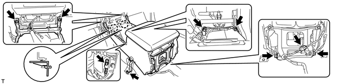
Attach the 2 claws.
Connect the connector.
Sufficiently apply compressor oil to 2 new O-rings.
- Compressor oil:
ND-OIL 8 or equivalent
Install the 2 O-rings on the 2 cooler pipes.
Connect the 2 cooler pipes with the 2 bolts.
- Torque:
- 5.4 N*m (55 kgf*cm, 48 in.*lbf)
Install the cooling box assembly with the 4 bolts and 2 screws.
86719A
2.INSTALL NO. 1 TELEPHONE BRACKET (w/ Telematics Transceiver)
86741A
3.INSTALL TELEMATICS TRANSCEIVER (w/ Telematics Transceiver)
58903A
4.INSTALL REAR CONSOLE END PANEL SUB-ASSEMBLY
88891H
5.INSTALL NO. 1 COOLER COVER
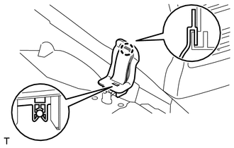
Attach the claw on the upper part of the cooler cover, and then attach the clamp on the lower part of the cooler cover to install it.
58804A
6.INSTALL UPPER CONSOLE PANEL SUB-ASSEMBLY
58805C
7.INSTALL REAR UPPER CONSOLE PANEL SUB-ASSEMBLY
58821C
8.INSTALL UPPER CONSOLE PANEL
58803C
9.INSTALL CONSOLE CUP HOLDER BOX SUB-ASSEMBLY
55406B
10.INSTALL LOWER CENTER INSTRUMENT CLUSTER FINISH PANEL SUB-ASSEMBLY
33504F
11.INSTALL SHIFT LEVER KNOB SUB-ASSEMBLY
55402C
12.INSTALL LOWER INSTRUMENT PANEL PAD SUB-ASSEMBLY RH
55448A
13.INSTALL NO. 1 INSTRUMENT PANEL FINISH CUSHION
55403C
14.INSTALL LOWER INSTRUMENT PANEL PAD SUB-ASSEMBLY LH
55449C
15.INSTALL NO. 2 INSTRUMENT PANEL FINISH PANEL CUSHION
71200S
16.INSTALL FRONT SEAT ASSEMBLY LH (for Manual Seat)
71200S
17.INSTALL FRONT SEAT ASSEMBLY LH (for Power Seat)
18.CHARGE REFRIGERANT
19.WARM UP ENGINE
20. CHECK FOR REFRIGERANT GAS LEAK
53292A
21.INSTALL UPPER RADIATOR SUPPORT SEAL