HEATING / AIR CONDITIONING AIR CONDITIONING SYSTEM(for Automatic Air Conditioning System) ECO Switch Circuit
DESCRIPTION
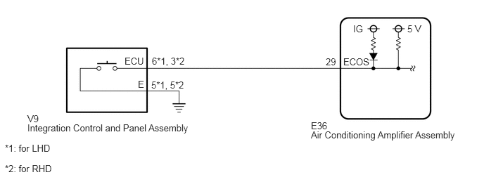
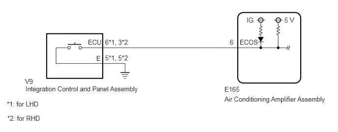
When the integration control and panel assembly is turned to ECO position, the air conditioning amplifier assembly controls the air conditioning system to enhance fuel efficiency.
WIRING DIAGRAM
w/ Rear Heater:
w/o Rear Heater:
PROCEDURE
Use the Data List to check if the integration control and panel assembly is functioning properly (See page Vehicle Interior>HEATING / AIR CONDITIONING>AIR CONDITIONING SYSTEM (for Automatic Air Conditioning System)>DATA LIST / ACTIVE TEST).
| Tester Display | Measurement Item/Range | Control Range | Diagnostic Note |
|---|---|---|---|
| ECO Switch | Integration control and panel assembly / OFF or ON | ON: Integration control and panel assembly being turned and held at ECO position
OFF: Integration control and panel assembly not turned |
- |
- OK:
The integration control and panel assembly condition displayed on the GTS changes with the actual switch operation.
OK
NG
Remove the integration control and panel assembly.
Inspect the integration control and panel assembly.
| Result | Proceed to |
|---|---|
| OK | A |
| NG (for AB60F) | B |
| NG (AC60F) | C |
A
B
C
w/ Rear Heater:
Disconnect the V9 integration control and panel assembly connector.
Disconnect the E36 air conditioning amplifier assembly connector.
Measure the resistance according to the value(s) in the table below.
- Standard Resistance:
- for LHD:
Tester Connection Condition Specified Condition V9-6 (ECU) - E36-29 (ECOS) Always Below 1 Ω V9-5 (E) - Body ground Always Below 1 Ω V9-6 (ECU) or E36-29 (ECOS) - Body ground Always 10 kΩ or higher
- for RHD:
Tester Connection Condition Specified Condition V9-3 (ECU) - E36-29 (ECOS) Always Below 1 Ω V9-5 (E) - Body ground Always Below 1 Ω V9-3 (ECU) or E36-29 (ECOS) - Body ground Always 10 kΩ or higher
w/o Rear Heater:
Disconnect the V9 integration control and panel assembly connector.
Disconnect the 165 air conditioning amplifier assembly connector.
Measure the resistance according to the value(s) in the table below.
- Standard Resistance:
- for LHD:
Tester Connection Condition Specified Condition V9-6 (ECU) - E165-6 (ECOS) Always Below 1 Ω V9-5 (E) - Body ground Always Below 1 Ω V9-6 (ECU) or E165-6 (ECOS) - Body ground Always 10 kΩ or higher
- for RHD:
Tester Connection Condition Specified Condition V9-3 (ECU) - E165-6 (ECOS) Always Below 1 Ω V9-5 (E) - Body ground Always Below 1 Ω V9-3 (ECU) or E165-6 (ECOS) - Body ground Always 10 kΩ or higher
OK
NG