1GR-FE ENGINE CONTROL IGNITION COIL AND SPARK PLUG INSTALLATION
CAUTION / NOTICE / HINT
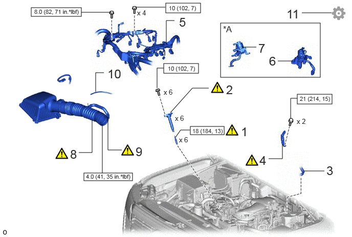
| Procedure | Part Name Code |

|

|

|
|
|---|---|---|---|---|---|
| 1 | SPARK PLUG | 19100P | ( ) |
- | - |
| 2 | IGNITION COIL ASSEMBLY | 19500 | () |
- | - |
| 3 | NO. 1 FUEL PIPE SUB-ASSEMBLY AND NO. 2 FUEL PIPE | 23801P | - | - | - |
| 4 | NO. 2 SURGE TANK STAY | 17126 | () |
- | - |
| 5 | ENGINE WIRE | 82121 | - | - | - |
| 6 | NO. 2 EMISSION CONTROL VALVE SET (w/ Secondary Air Injection System) | 25702B | - | - | - |
| 7 | NO. 1 EMISSION CONTROL VALVE SET (w/ Secondary Air Injection System) | 25701B | - | - | - |
| 8 | AIR CLEANER CAP WITH AIR CLEANER HOSE | 17735 | () |
- | - |
| 9 | NO. 2 VENTILATION HOSE | 12262 | () |
- | - |
| 10 | VACUUM TRANSMITTING HOSE ASSEMBLY | 25760 | - | - | - |
| 11 | PERFORM INITIALIZATION | - | - | - | () |
| *A | w/ Secondary Air Injection System | - | - |

|
N*m (kgf*cm, ft.*lbf): Specified torque | - | - |
PROCEDURE

 19100P 1.INSTALL SPARK PLUG
|
|
Click here() |
19500 2.INSTALL IGNITION COIL ASSEMBLY
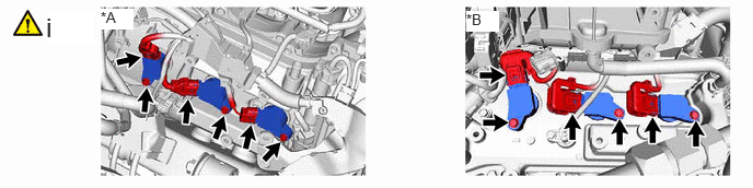
| *A | Bank 1 | *B | Bank 2 |
Install the 6 ignition coil assemblies to the cylinder head cover sub-assembly with the 6 bolts.
- Torque:
- 10 N*m (102 kgf*cm, 7 ft.*lbf)
- NOTICE:
-
If an ignition coil assembly has been struck or dropped, replace it.
Connect the 6 ignition coil assembly connectors.
23801P 3.INSTALL NO. 1 FUEL PIPE SUB-ASSEMBLY AND NO. 2 FUEL PIPE
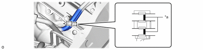
| *a | Paint Mark | - | - |
Install the No. 1 fuel pipe sub-assembly and No. 2 fuel pipe to the clamp.
- NOTICE:
-
Align the paint mark with the end of the clamp.
17126 4.INSTALL NO. 2 SURGE TANK STAY

Install the 2 bolts in the order shown in the illustration.
- Torque:
- 21 N*m (214 kgf*cm, 15 ft.*lbf)
82121 5.INSTALL ENGINE WIRE


|
Bolt A |

|
Bolt B |
- Torque:
- for bolt A : 10 N*m (102 kgf*cm, 7 ft.*lbf)
- for bolt B : 8.0 N*m (82 kgf*cm, 71 in.*lbf)
25702B 6.INSTALL NO. 2 EMISSION CONTROL VALVE SET (w/ Secondary Air Injection System)
25701B 7.INSTALL NO. 1 EMISSION CONTROL VALVE SET (w/ Secondary Air Injection System)
17735 8.INSTALL AIR CLEANER CAP WITH AIR CLEANER HOSE
|
|
Click here() |
12262 9.INSTALL NO. 2 VENTILATION HOSE
|
|
Click here() |
25760 10.INSTALL VACUUM TRANSMITTING HOSE ASSEMBLY
11.PERFORM INITIALIZATION
Perform "Inspection After Repair" after replacing an ignition coil assembly or spark plug.
Click hereEngine / Hybrid System>1GR-FE (ENGINE CONTROL)>SFI SYSTEM>INITIALIZATION