POWER DISTRIBUTION POWER INTEGRATION SYSTEM TERMINALS OF ECU
- NOTICE:
-
·
After turning the ignition switch off, waiting time may be required before disconnecting the cable from the negative (-) battery terminal.
Click hereGeneral>SETUP>WHEN DISCONNECTING OR RECONNECTING BATTERY TERMINAL>BEFORE DISCONNECTING BATTERY
·When disconnecting and reconnecting the battery.
Click hereGeneral>SETUP>WHEN DISCONNECTING OR RECONNECTING BATTERY TERMINAL>WORK PROCEDURE
- HINT:
-
When disconnecting and reconnecting the battery, there is an automatic learning function that completes learning when the respective system is used.
-
Click hereGeneral>SETUP>WHEN DISCONNECTING OR RECONNECTING BATTERY TERMINAL>AUTOMATIC LEARNING CHART
CHECK POWER DISTRIBUTION BOX ASSEMBLY AND MAIN BODY ECU (MULTIPLEX NETWORK BODY ECU)
Remove the main body ECU (multiplex network body ECU) from the power distribution box assembly.
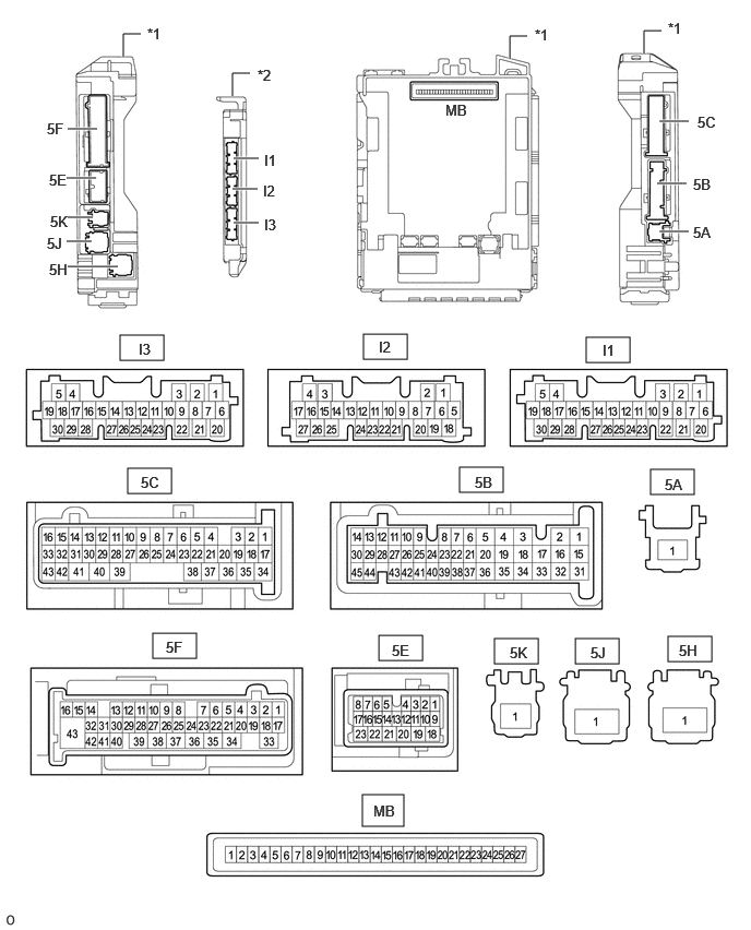
| *1 | Power Distribution Box Assembly | *2 | Main Body ECU (Multiplex Network Body ECU) |
for RHD:
Click herePower Source / Network>POWER DISTRIBUTION>MAIN BODY ECU (for RHD)>REMOVAL
for LHD:
Click herePower Source / Network>POWER DISTRIBUTION>MAIN BODY ECU (for LHD)>REMOVAL
Reconnect the power distribution box assembly connectors.
Measure the voltage and resistance according to the value(s) in the table below.
| Terminal No. (Symbol) | Terminal Description | Condition | Specified Condition |
|---|---|---|---|
| MB-13 (GND1) - Body ground | Ground | Always | Below 1 Ω |
| MB-26 (BECU) - Body ground | Battery power supply | Always | 11 to 14 V |
| MB-27 (IGR) - Body ground | IG power supply | Ignition switch off | Below 1 V |
| Ignition switch ON | 11 to 14 V |
Install the main body ECU (multiplex network body ECU) to the power distribution box assembly.
Measure the voltage and resistance, check for pulses according to the value(s) in the table below.
| Terminal No. (Symbol) | Terminal Description | Condition | Specified Condition |
|---|---|---|---|
| 5E-5 - Body ground | CXPI communication line | Ignition switch ON | Pulse generation |
| Ignition switch ON | Below 1 V | ||
| 5F-43 - Body ground | Rear window defogger signal (output) | rear window defogger switch off | Below 1.5 V |
| rear window defogger switch on | 8 to 14 V | ||
| 4B-2 - Body ground*1 | Mirror heater drive voltage (output) | Ignition switch ON, rear defogger switch off | Below 1.5 V |
| Ignition switch ON, rear defogger switch on | 8 to 14 V | ||
| 5F-7 - Body ground | Taillights drive output | Taillights off | Below 1 V |
| Taillights on | 11 to 14 V | ||
| 5F-28 - Body ground | Front fog lights drive output | Taillights on, fog light switch in off position | Below 1 V |
| Taillights on, fog light switch in front position | 11 to 14 V | ||
| 5F-30 - Body ground*2 | Rear fog lights drive output | Taillights on, fog light switch in off position | Below 1 V |
| Taillights on, fog light switch in rear position | 11 to 14 V | ||
| 5C-1 - Body ground | Each instrument panel illumination power supply | Light control switch in neither tail or head position | Below 1 V |
| Light control switch in tail or head position | 11 to 14 V | ||
| 5F-9 - Body ground | Each instrument panel illumination power supply | Light control switch in neither tail or head position | Below 1 V |
| Light control switch in tail or head position | 11 to 14 V | ||
| 5B-44 - Body ground | Ground | Always | Below 1 Ω |
| 5C-25 - Body ground | Ground | Always | Below 1 Ω |
*1: w/ Mirror Heater
*2: w/ Rear Fog Light
CHECK SEMICONDUCTOR POWER INTEGRATION ECU

| *a | Component without harness connected (Semiconductor Power Integration ECU) |
- | - |
Disconnect the cable from the negative (-) battery terminal.
Disconnect the B58 and B57 semiconductor power integration ECU connectors.
Connect the cable to the negative (-) battery terminal.
Measure the resistance and voltage according to the value(s) in the table below.
| Terminal No. (Symbol) | Terminal Description | Condition | Specified Condition |
|---|---|---|---|
| B58-1 (+B) - Body ground | Battery power supply | Always | 8 to 14 V |
| B57-15 (-S) - Body ground | Headlight ECU sub-assembly operation signal input | Ignition switch off | 6 V or higher |
| Ignition switch ON | Below 1.7 V | ||
| B57-6 (GND2) - Body ground | Ground | Always | Below 1 Ω |
| B57-9 (IG) - Body ground | IG power supply | Ignition switch off | Below 1.5 V |
| Ignition switch ON | 8 to 14 V | ||
| B57-14 (-S) - Body ground | Headlight ECU sub-assembly operation signal input | Ignition switch off | 6 V or higher |
| Ignition switch ON | Below 1.7 V | ||
| B57-13 (GND1) - Body ground | Ground | Always | Below 1 Ω |
Reconnect the B58 and B57 semiconductor power integration ECU connectors.
Measure the voltage and check for pulses according to the value(s) in the table below.
| Terminal No. (Symbol) | Terminal Description | Condition | Specified Condition |
|---|---|---|---|
| B57-7 (CXPI) - Body ground | CXPI communication line | Ignition switch ON | Pulse generation |
| B57-1 (L) - Body ground | Headlight ECU sub-assembly LH power supply | Ignition switch off | Below 3.0 V |
| Ignition switch ON | 8 V or higher | ||
| B57-2 (L)- Body ground | Headlight ECU sub-assembly RH power supply | Ignition switch off | Below 3.0 V |
| Ignition switch ON | 8 V or higher | ||
| B57-3 (L) - Body ground | Power w/p output | Ignition switch off | Below 3.0 V |
| Ignition switch ON | 8 V or higher | ||
| B57-4 (L) - Body ground | Magnetic clutch output | Ignition switch off | Below 3.0 V |
| Ignition switch ON | 8 V or higher | ||
| B57-5 (-S) - Body ground | Magnetic clutch input | Ignition switch off | Below 3.0 V |
| Ignition switch ON | 8 V or higher | ||
| B57-12 (WLVL) - Body ground | Level warning switch assembly input | Ignition switch ON, washer fluid volume is 600 cc (36.6 cu.in.) or lower | Below 3.0 V |
| Ignition switch ON, washer fluid volume is 800 cc (48.8 cu.in.) or higher | 8 V or higher | ||
| B57-17 (L) - Body ground | Front fog light output | Front fog light not illuminated | Below 3.0 V |
| Front fog light illuminated | 8 V or higher |