PARK ASSIST / MONITORING TELEVISION CAMERA(for Side) INSTALLATION
CAUTION / NOTICE / HINT
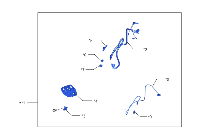
| *1 | HARNESS ASSEMBLY | *2 | HARNESS SUB-ASSEMBLY |
| *3 | HOOK | *4 | GASKET |
| *5 | WIRE HARNESS CLAMP | *6 | HARNESS CLAMP |
| *7 | CONNECTOR HOUSING | *8 | TELEVISION CAMERA WIRE |
| *9 | ADAPTER | - | - |
| ● | Non-reusable part | - | - |
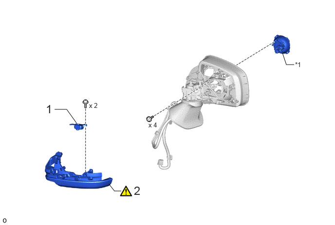
| Procedure | Part Name Code |

|

|

|
|
|---|---|---|---|---|---|
| 1 | SIDE TELEVISION CAMERA ASSEMBLY LH | 86790F | - | - | - |
| 2 | COVER BODY | - | ( ) |
- | - |
| *1 | ACTUATOR SUB-ASSEMBLY | - | - |
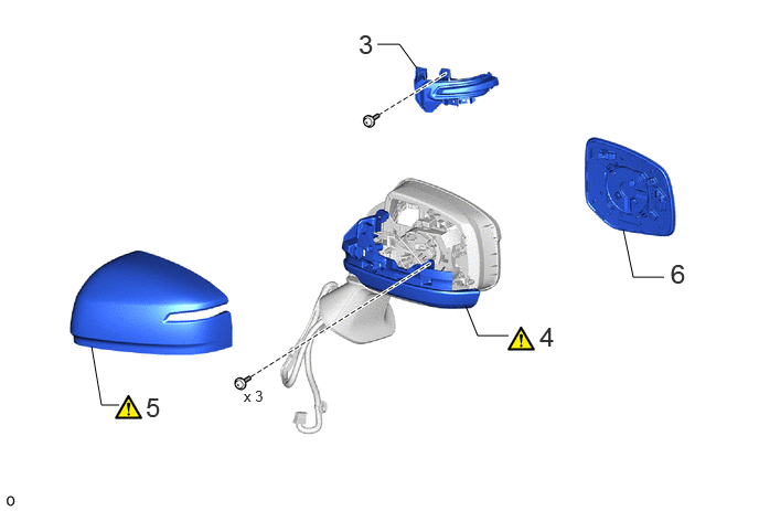
| Procedure | Part Name Code |
|
|
|
|
|---|---|---|---|---|---|
| 3 | SIDE TURN SIGNAL LIGHT ASSEMBLY LH | 81740 | - | - | - |
| 4 | COVER BODY | - | () |
- | - |
| 5 | OUTER MIRROR COVER LH | 87945 | () |
- | - |
| 6 | OUTER MIRROR LH | 87961 | - | - | - |

| Procedure | Part Name Code |
|
|
|
|
|---|---|---|---|---|---|
| 7 | OUTER REAR VIEW MIRROR ASSEMBLY LH | 87940 | - | - | - |
| 8 | ADJUST SIDE TELEVISION CAMERA ASSEMBLY LH | - | - | - | () |
CAUTION / NOTICE / HINT
- HINT:
-
·
Use the same procedure for the RH and LH sides.
·The procedure listed below is for the LH side.
PROCEDURE

 86790F 1.INSTALL SIDE TELEVISION CAMERA ASSEMBLY LH
2.INSTALL COVER BODY
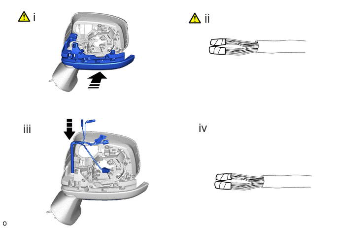

|
Install in this Direction | - | - |
Temporarily install the cover body as shown in the illustration.
Wind vinyl tape around the harness sub-assembly to secure it as shown in the illustration.
Insert the harness sub-assembly and the television camera wire through the outer mirror body as shown in the illustration.
Remove the vinyl tape.
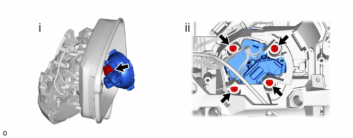
Connect the connector.
Install the actuator sub-assembly with 4 screws.
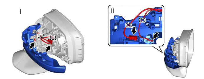
Connect the 2 connectors and attach the guide.
Attach the clamp and connect the 2 connectors.
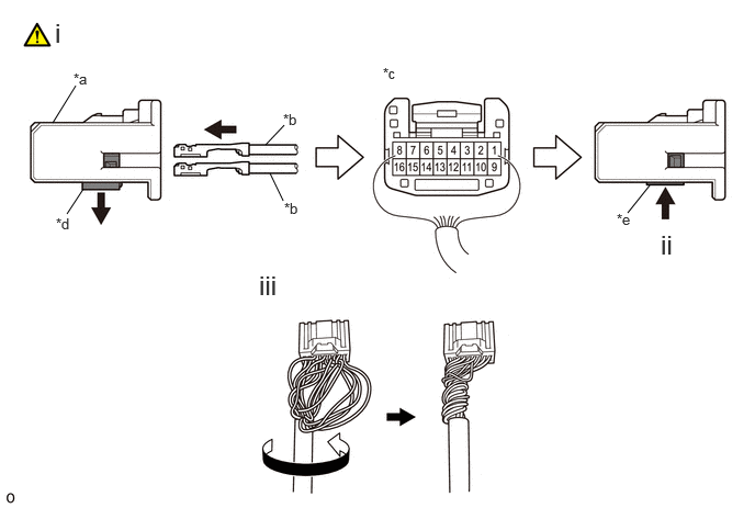
| *a | Connector Housing | *b | Wire Harness Pin |
| *c | Back View of Wire Harness Connector | *d | Retainer Unlock Position |
| *e | Retainer Lock Position | - | - |
Insert wire harness pins from the backside of the adapter until they lock.
- Wire Harness Color Chart:
-
1 2 3 4 5 6 7 8 PURPLE GREEN-RED SKY BLUE BLACK-GREEN
*1ORANGE WHITE-BLACK BLUE-YELLOW
*2BLACK-RED
*3
- Wire Harness Color Chart:
-
9 10 11 12 13 14 15 16 BROWN RED LIGHT GREEN WHITE YELLOW-BLACK GRAY BLACK-BROWN
*2PINK
*1: w/ Mirror Heater
*2: w/ EC Mirror
*3: w/ Blind Spot Monitor System
Set the retainer to the lock position.
- NOTICE:
-
·
When inserting the wire harness pins, compare with the connector that was cut off during removal to verify the insertion positions, and then make sure to insert the pins of the correct wire colors in the correct positions.
·Make sure that the wire harness pins are securely locked in position and cannot be removed.
·The wire harness pins cannot be removed after they have locked into place, so be absolutely certain to insert them in the correct positions.
Route the longer part of the wire harness sub-assembly as shown in the illustration.
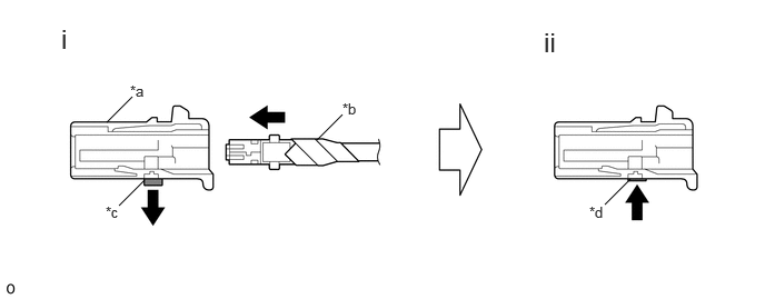
| *a | Adapter | *b | Television Camera Wire |
| *c | Retainer Unlock Position | *d | Retainer Lock Position |
Connect the television camera wire connector to the adapter.
Set the retainer to the lock position.
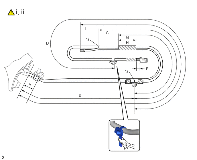
| *a | Marking | - | - |

|
Vinyl Tape | - | - |
Adjust the wire harness clamp and harness clamp so that the marking is at the position shown in the illustration to install it.
- Standard Measurement:
-
Area Measurement A 30 mm (1.18 in.) B 294 to 314 mm (11.57 in. to 1.03 ft.) C 187 to 207 mm (7.36 to 8.15 in.) D 404 to 414 mm (1.33 to 1.36 ft.) E Below 20 mm (0.787 in.) F 571 to 591 mm (1.87 to 1.94 ft.) G 142 mm (5.59 in.) H 50 mm (1.97 in.)
Using a nipper, cut the position shown in the illustration.
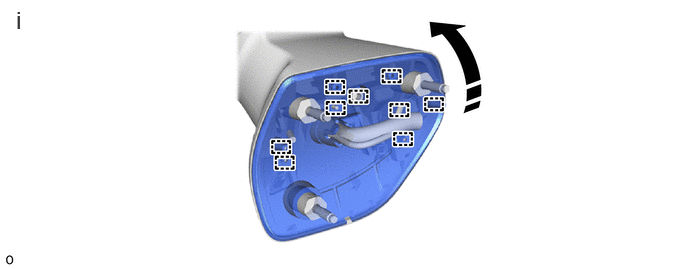
|
|
Install in this Direction | - | - |
Attach the guide to install the gasket.
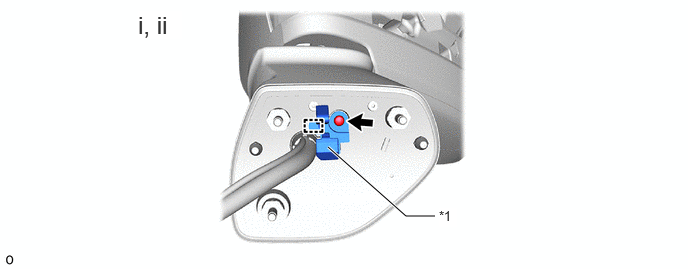
| *1 | Hook | - | - |
Attach the guide and install the hook.
Install the screw.
81740 3.INSTALL SIDE TURN SIGNAL LIGHT ASSEMBLY LH
4.INSTALL COVER BODY
|
|
Click here() |
87945 5.INSTALL OUTER MIRROR COVER LH
|
|
Click here() |
87961 6.INSTALL OUTER MIRROR LH
87940 7.INSTALL OUTER REAR VIEW MIRROR ASSEMBLY LH
86790F 8.ADJUST SIDE TELEVISION CAMERA ASSEMBLY LH