JF2BM TRANSFER / 4WD / AWD TRANSFER ASSEMBLY REASSEMBLY
CAUTION / NOTICE / HINT
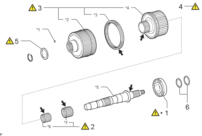
| Procedure | Part Name Code |

|

|

|
|
|---|---|---|---|---|---|
| 1 | TRANSFER OUTPUT SHAFT REAR RADIAL BALL BEARING | 36231J | ( ) |
- | - |
| 2 | TRANSFER DRIVE SPROCKET BEARING | 36291A | () |
- | - |
| 3 | CENTER DIFFERENTIAL CASE AND FRONT DRIVE CLUTCH SLEEVE, TRANSFER DRIVE SPROCKET SUB-ASSEMBLY | - | () |
- | - |
| 4 | INSPECT TRANSFER DRIVE SPROCKET SUB-ASSEMBLY | 36205 | () |
- | - |
| 5 | NO. 1 TRANSFER OUTPUT SHAFT SPACER | 36255 | () |
- | - |
| 6 | TRANSFER OUTPUT SHAFT WASHER | 33309H | - | - | - |
| *1 | STRAIGHT PIN | *2 | CENTER DIFFERENTIAL CASE |
| *3 | FRONT DRIVE CLUTCH SLEEVE | *4 | TRANSFER DRIVE SPROCKET SUB-ASSEMBLY |
| *5 | REAR TRANSFER OUTPUT SHAFT | *6 | TRANSFER DRIVE SPROCKET BEARING (FRONT SIDE) |
| *7 | TRANSFER DRIVE SPROCKET BEARING (REAR SIDE) | - | - |
| ● | Non-reusable part |

|
Transfer oil |
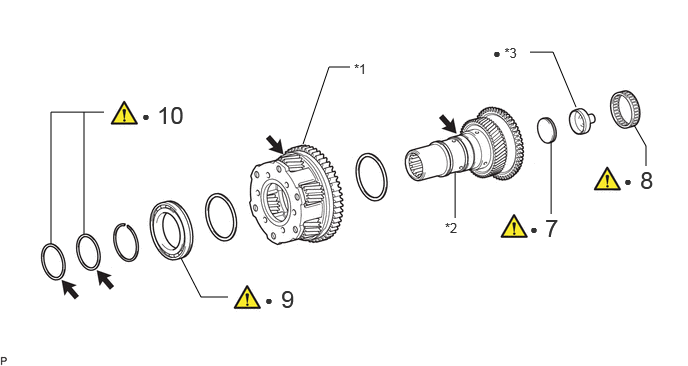
| Procedure | Part Name Code |
|
|
|
|
|---|---|---|---|---|---|
| 7 | TRANSFER INPUT SHAFT PLUG | 36218C | () |
- | - |
| 8 | TRANSFER INPUT GEAR NEEDLE ROLLER BEARING | 36212B | () |
- | - |
| 9 | TRANSFER INPUT SHAFT BEARING | 36210A | () |
- | - |
| 10 | NO. 1 TRANSFER INPUT SHAFT SEAL RING | 36216A | () |
- | - |
| *1 | TRANSFER LOW PLANETARY GEAR ASSEMBLY | *2 | TRANSFER INPUT SHAFT |
| *3 | TRANSFER OIL RECEIVER | - | - |
| ● | Non-reusable part |
|
Transfer oil |
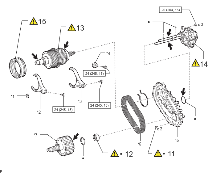
| Procedure | Part Name Code |
|
|
|
|
|---|---|---|---|---|---|
| 11 | TRANSFER CASE STRAIGHT PIN | 36111G | () |
- | - |
| 12 | SIDE GEAR SHAFT HOLDER BEARING | 41335D | () |
- | - |
| 13 | REAR TRANSFER OUTPUT SHAFT ASSEMBLY | - | () |
- | - |
| 14 | TRANSFER SHIFT ACTUATOR ASSEMBLY | 36410J | () |
- | - |
| 15 | TRANSFER HIGH AND LOW CLUTCH SLEEVE | 36235 | () |
- | - |
| *1 | NO. 2 TRANSFER SHIFT SHAFT STOPPER | *2 | NO. 2 TRANSFER GEAR SHIFT FORK |
| *3 | NO. 1 TRANSFER GEAR SHIFT FORK | *4 | TRANSFER SHIFT SHAFT STOPPER |
| *5 | REAR TRANSFER CASE | *6 | TRANSFER FRONT DRIVE CHAIN |
| *7 | TRANSFER DRIVEN SPROCKET | - | - |

|
N*m (kgf*cm, ft.*lbf): Specified torque | ● | Non-reusable part |
|
|
Transfer oil | - | - |
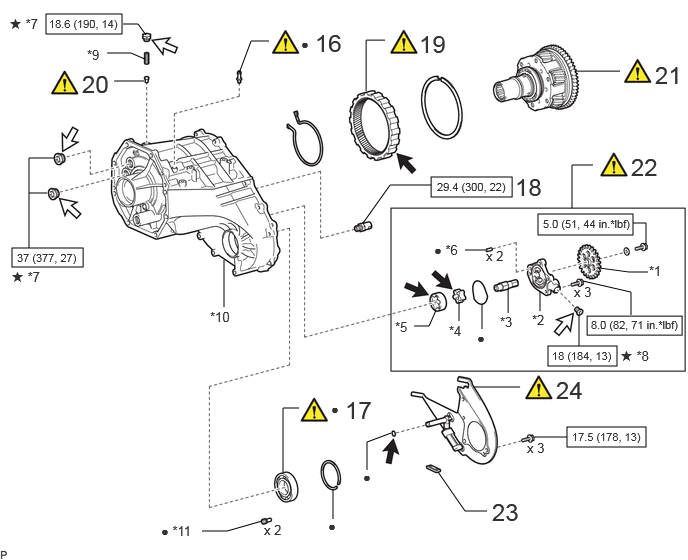
| Procedure | Part Name Code |
|
|
|
|
|---|---|---|---|---|---|
| 16 | TRANSFER CASE TUBE | 36111T | () |
- | - |
| 17 | TRANSFER DRIVEN SPROCKET BEARING | 36292A | () |
- | - |
| 18 | TRANSFER OIL PUMP RELIEF VALVE SUB-ASSEMBLY | - | - | - | - |
| 19 | TRANSFER LOW PLANETARY RING GEAR | 36273 | () |
- | - |
| 20 | TRANSFER CASE SLOTTED SPRING PIN | 36111M | () |
- | - |
| 21 | TRANSFER INPUT SHAFT ASSEMBLY | - | () |
- | - |
| 22 | TRANSFER OIL PUMP ROTOR SET | 36106L | () |
- | - |
| 23 | TRANSFER CASE MAGNET | 33449D | - | - | - |
| 24 | TRANSFER OIL SEPARATOR SUB-ASSEMBLY | - | () |
- | - |
| *1 | OIL PUMP GEAR | *2 | OIL PUMP PLATE SUB-ASSEMBLY |
| *3 | OIL PUMP SHAFT | *4 | OIL PUMP DRIVE ROTOR |
| *5 | OIL PUMP DRIVEN ROTOR | *6 | STRAIGHT PIN |
| *7 | TRANSFER CASE PLUG | *8 | STRAIGHT SCREW PLUG |
| *9 | TRANSFER CASE COMPRESSION SPRING | *10 | FRONT TRANSFER CASE |
| *11 | PIN | - | - |
|
|
N*m (kgf*cm, ft.*lbf): Specified torque | ● | Non-reusable part |
|
|
Transfer oil |

|
Toyota Genuine Adhesive 1344, Three Bond 1344 or equivalent |
| ★ | Precoated part | - | - |
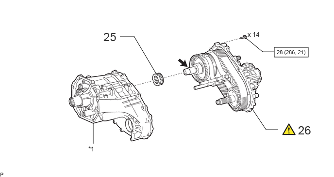
| Procedure | Part Name Code |
|
|
|
|
|---|---|---|---|---|---|
| 25 | FRONT TRANSFER OUTPUT SHAFT NEEDLE ROLLER BEARING | 36231E | - | - | - |
| 26 | REAR TRANSFER CASE | 36112 | () |
- | - |
| *1 | FRONT TRANSFER CASE | - | - |
|
|
N*m (kgf*cm, ft.*lbf): Specified torque |
|
Transfer oil |
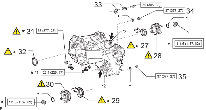
| Procedure | Part Name Code |
|
|
|
|
|---|---|---|---|---|---|
| 27 | TRANSFER COVER TYPE T OIL SEAL | 36102J | () |
- | - |
| 28 | OUTPUT SHAFT COMPANION FLANGE SUB-ASSEMBLY (REAR) | 33309B | () |
- | - |
| 29 | TRANSFER CASE OIL SEAL | 36111B | () |
- | - |
| 30 | OUTPUT SHAFT COMPANION FLANGE SUB-ASSEMBLY (FRONT) | 33309C | () |
- | - |
| 31 | TRANSFER CASE PLUG | - | () |
- | - |
| 32 | TRANSFER EXTENSION HOUSING TYPE T OIL SEAL | 36115C | () |
- | - |
| 33 | PROPELLER SHAFT HEAT INSULATOR BRACKET SUB-ASSEMBLY | 37109A | - | - | - |
| 34 | FILLER PLUG | - | - | - | - |
| 35 | DRAIN PLUG | - | - | - | - |
| *1 | NO. 2 TRANSFER CASE PLUG | *2 | TRANSFER DRIVEN SPROCKET |
| *3 | REAR TRANSFER OUTPUT SHAFT | - | - |

|
Tightening torque for "Major areas involving basic vehicle performance such as moving/turning/stopping": N*m (kgf*cm, ft.*lbf) |
|
N*m (kgf*cm, ft.*lbf): Specified torque |
| ● | Non-reusable part |
|
Transfer oil |
|
|
MP grease |

|
Toyota Genuine Adhesive 1344, Three Bond 1344 or equivalent |
| ★ | Precoated part | - | - |
PROCEDURE

 36231J 1.INSTALL TRANSFER OUTPUT SHAFT REAR RADIAL BALL BEARING
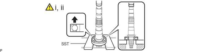
|
|
Front Side | - | - |
Apply transfer oil to the bearing press-fit portion.
Using SST and a press, press in a new transfer output shaft rear radial ball bearing.
- SST
-
09527-10011
- NOTICE:
-
Set the transfer output shaft snap ring groove of the transfer output shaft rear radial ball bearing to the front side.
36291A 2.INSTALL TRANSFER DRIVE SPROCKET BEARING
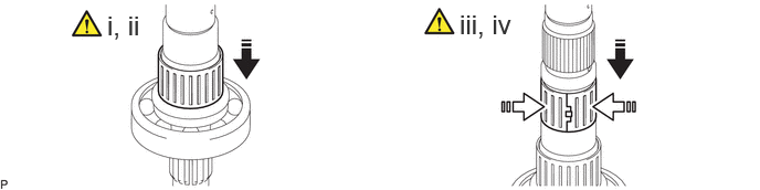

|
Install in this direction |

|
Close the opening |
Apply transfer oil to the transfer drive sprocket bearing (rear side).
Install the transfer drive sprocket bearing (rear side) to the rear transfer output shaft.
Apply transfer oil to the transfer drive sprocket bearing (front side).
Install the transfer drive sprocket bearing (front side) to the rear transfer output shaft as shown in the illustration.
3.INSTALL CENTER DIFFERENTIAL CASE AND FRONT DRIVE CLUTCH SLEEVE, TRANSFER DRIVE SPROCKET SUB-ASSEMBLY
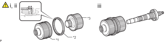
| *1 | Center Differential Case | *2 | Front Drive Clutch Sleeve |
| *3 | Transfer Drive Sprocket Sub-assembly | - | - |
Apply transfer oil to the fitting surfaces of the thrust, hub and sleeve.
Install the front drive clutch sleeve and transfer drive sprocket sub-assembly to the center differential case.
- NOTICE:
-
Make sure the front drive clutch sleeve is installed in the correct direction.
Install the center differential case and front drive clutch sleeve, transfer drive sprocket sub-assembly to the rear transfer output shaft.
36205 4.INSPECT TRANSFER DRIVE SPROCKET SUB-ASSEMBLY
|
|
() |
36255 5.INSTALL NO. 1 TRANSFER OUTPUT SHAFT SPACER
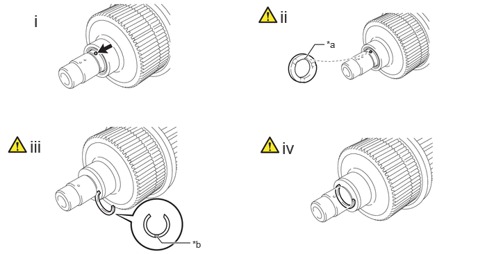
| *a | Cutout | *b | Identification Mark |
Install the straight pin to the rear transfer output shaft.
As shown in the illustration, align the straight pin with the cutout on the No. 1 transfer output shaft spacer, and install the No. 1 transfer output shaft spacer.
Select a transfer input gear shaft snap ring so that the thrust clearance of the center differential case and rear transfer output shaft is as specified.
- Standard Thrust Clearance:
-
0.1 mm (0.00394 in.) or less
- HINT:
-
Standard Transfer Input Gear Shaft Snap Ring Thickness
-
Mark Thickness A 2.47 to 2.52 mm (0.0973 to 0.0992 in.) B 2.52 to 2.57 mm (0.0993 to 0.1011 in.) C 2.57 to 2.62 mm (0.1012 to 0.1031 in.) D 2.62 to 2.67 mm (0.1032 to 0.1051 in.) E 2.67 to 2.72 mm (0.1052 to 0.1070 in.) F 2.72 to 2.77 mm (0.1071 to 0.1090 in.) G 2.77 to 2.82 mm (0.1091 to 0.1110 in.) H 2.82 to 2.87 mm (0.1111 to 0.1129 in.) J 2.87 to 2.92 mm (0.1130 to 0.1149 in.) K 2.92 to 2.97 mm (0.1150 to 0.1169 in.) L 2.97 to 3.02 mm (0.1170 to 0.1189 in.) M 3.02 to 3.07 mm (0.1190 to 0.1208 in.) N 3.07 to 3.12 mm (0.1209 to 0.1228 in.)
Using a hammer, tap on the transfer input gear shaft snap ring.
33309H 6.INSTALL TRANSFER OUTPUT SHAFT WASHER
36218C 7.INSTALL TRANSFER INPUT SHAFT PLUG
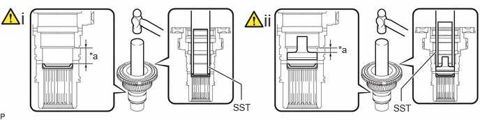
| *a | Standard Depth | - | - |
Using SST and hammer, install a new transfer input shaft plug to the transfer input shaft as shown in the illustration.
- SST
-
09608-04031
- Standard Depth:
-
22.3 to 23.1 mm (0.879 to 0.909 in.)
- NOTICE:
-
Be careful not to damage or deform the transfer input shaft plug when tapping it.
Using SST and hammer, install a new transfer oil receiver to the transfer input shaft as shown in the illustration.
- SST
-
09608-04031
- Standard Depth:
-
3.9 to 4.7 mm (0.154 to 0.185 in.)
- NOTICE:
-
Be careful not to damage or deform the transfer oil receiver when tapping it.
36212B 8.INSTALL TRANSFER INPUT GEAR NEEDLE ROLLER BEARING
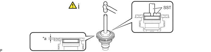
| *a | Standard Depth | - | - |
Using SST and hammer, install a new transfer input gear needle roller bearing to the transfer input shaft as shown in the illustration.
- SST
-
09950-70010 (09951-07150)
09950-60011 (09951-00610)
- Standard Depth:
-
4.8 to 5.2 mm (0.190 to 0.204 in.)
- NOTICE:
-
Be careful not to damage the transfer input shaft.
36210A 9.INSTALL TRANSFER INPUT SHAFT BEARING
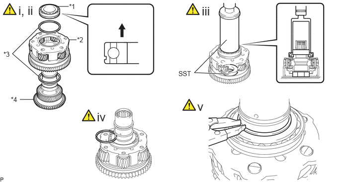
| *1 | Transfer Input Shaft Bearing | *2 | Transfer Low Planetary Gear Assembly |
| *3 | Manual Transfer Planetary Carrier Washer | *4 | Transfer Input Shaft |
|
|
Front Side | - | - |
Apply transfer oil to the bearing press-fit portion and pinion gear.
Install a new transfer input shaft bearing and transfer low planetary gear assembly, 2 manual transfer planetary carrier washers to the transfer input shaft.
- NOTICE:
-
Make sure the transfer input shaft bearing is installed in the correct direction.
Using SST and a press, press in the transfer input shaft bearing.
- SST
-
09513-36040
09515-21010
- NOTICE:
-
After press-fitting the transfer input shaft bearing to the transfer input shaft, check that the transfer input shaft bearing moves smoothly.
Select a transfer input bearing shaft snap ring so that the thrust clearance of the transfer input shaft bearing and transfer input shaft is as specified.
- Standard Thrust Clearance:
-
0.1 mm (0.00394 in.) or less
- HINT:
-
Standard Transfer Input Bearing Shaft Snap Ring Thickness
-
Mark Thickness K 2.13 to 2.18 mm (0.0839 to 0.0858 in.) L 2.18 to 2.23 mm (0.0858 to 0.0878 in.) M 2.23 to 2.28 mm (0.0878 to 0.0898 in.) N 2.28 to 2.33 mm (0.0898 to 0.0917 in.) P 2.33 to 2.38 mm (0.0917 to 0.0937 in.) Q 2.38 to 2.43 mm (0.0937 to 0.0957 in.) R 2.43 to 2.48 mm (0.0957 to 0.0976 in.)
Using a snap ring expander, install the transfer input bearing shaft snap ring.
36216A 10.INSTALL NO. 1 TRANSFER INPUT SHAFT SEAL RING

Apply transfer oil to the 2 new No. 1 transfer input shaft seal rings.
Install the 2 No. 1 transfer input shaft seal rings to the transfer input shaft.
36111G 11.INSTALL TRANSFER CASE STRAIGHT PIN
- HINT:
-
There is no need to install this unless the transfer case straight pin is replaced.

| *a | Standard Protrusion Height | - | - |
Using a plastic-faced hammer, tap in 2 new transfer case straight pins to the standard protrusion amount.
- Standard Protrusion Height:
-
6.5 to 7.5 mm (0.256 to 0.295 in.)
41335D 12.INSTALL SIDE GEAR SHAFT HOLDER BEARING
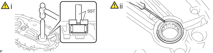
Using SST and a hammer, tap in a new side gear shaft holder bearing to the rear transfer case.
- SST
-
09950-60011 (09951-00520)
09950-70010 (09951-07100)
Using a screwdriver, install a new transfer driven sprocket snap ring.
13.INSTALL REAR TRANSFER OUTPUT SHAFT ASSEMBLY
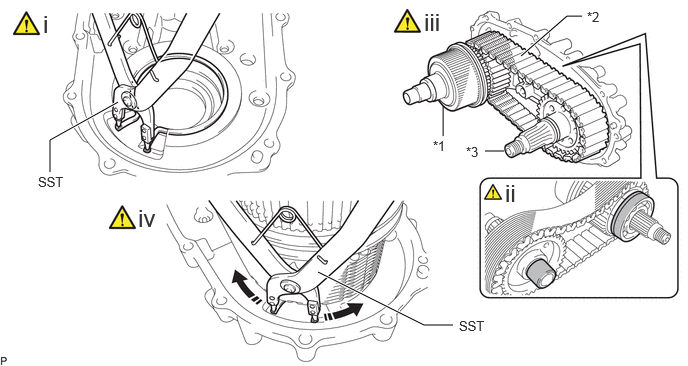
| *1 | Rear Transfer Output Shaft Assembly | *2 | Transfer Front Drive Chain |
| *3 | Transfer Driven Sprocket | - | - |
|
|
Expand |

|
Transfer Oil |
Using SST, install the transfer output shaft snap ring to the rear transfer case.
- SST
-
09350-32014 (09351-32050)
Apply transfer oil to the rear transfer output shaft assembly and transfer driven sprocket at the points shown in the illustration.
Install the rear transfer output shaft assembly, transfer front drive chain and transfer driven sprocket.
- NOTICE:
-
Do not drop the transfer output shaft washers.
Using SST, install the transfer output shaft snap ring to the rear transfer output shaft assembly.
- SST
-
09350-32014 (09351-32050)
36410J 14.INSTALL TRANSFER SHIFT ACTUATOR ASSEMBLY
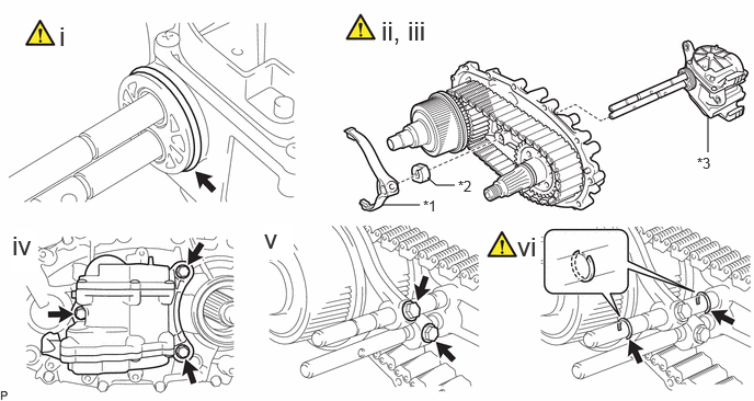
| *1 | No. 1 Transfer Gear Shift Fork | *2 | Transfer Shift Shaft Stopper |
| *3 | Transfer Shift Actuator Assembly | - | - |
Coat a new O-ring with the transfer oil install it to the transfer shift actuator assembly.
Apply transfer oil to the shaft sliding parts.
Temporarily install the transfer shift actuator assembly and No. 1 transfer gear shift fork, transfer shift shaft stopper.
Install the transfer shift actuator assembly with the 3 bolts.
- Torque:
- 20 N*m (204 kgf*cm, 15 ft.*lbf)
Install the No. 1 transfer gear shift fork and transfer shift shaft stopper to the transfer shift actuator assembly with the 2 bolts.
- Torque:
- 24 N*m (245 kgf*cm, 18 ft.*lbf)
Using a screwdriver and hammer, tap 2 new transfer gear shift fork snap rings.
- NOTICE:
-
After installing the transfer gear shift fork snap ring, replace it with a new one if there is any clearance along the inside diameter.
36235 15.INSTALL TRANSFER HIGH AND LOW CLUTCH SLEEVE
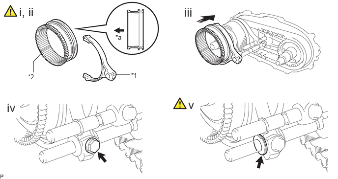
| *1 | No. 2 Transfer Gear Shift Fork | *2 | Transfer High and Low Clutch Sleeve |
| *a | Front Side | - | - |
|
|
Install in this direction | - | - |
Apply transfer oil to the shaft sliding parts.
Install the transfer high and low clutch sleeve to the No. 2 transfer gear shift fork.
- NOTICE:
-
Make sure to install the transfer high and low clutch sleeve in the correct direction.
Install the No. 2 transfer gear shift fork and transfer high-and-low clutch sleeve in the direction of the arrow shown in the illustration.
Install the No. 2 gear shift fork to the transfer shift actuator assembly with the bolt.
- Torque:
- 24 N*m (245 kgf*cm, 18 ft.*lbf)
Install the No. 2 transfer shift shaft stopper.
- NOTICE:
-
Ensure that it makes full contact with the No. 2 transfer gear shift fork.
36111T 16.INSTALL TRANSFER CASE TUBE
- HINT:
-
There is no need to install this unless the transfer case tube is replaced.
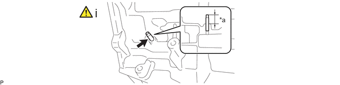
| *a | Standard Protrusion Height | - | - |
Using a plastic-faced hammer, tap in a new transfer case tube to the standard protrusion amount.
- Standard Protrusion Height:
-
14.5 to 15.5 mm (0.571 to 0.610 in.)
36292A 17.INSTALL TRANSFER DRIVEN SPROCKET BEARING
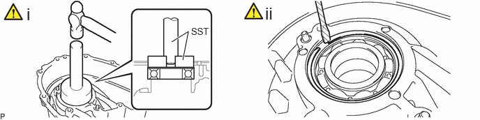
Using a hammer and SST, install a new transfer driven sprocket bearing to the front transfer case.
- SST
-
09950-70010 (09951-07150)
09950-60021 (09951-00780)
- NOTICE:
-
Install the transfer driven sprocket bearing with the shielded surface on the front side.
Using a screwdriver, install a new transfer driven sprocket snap ring.

| *a | Standard Protrusion Height | - | - |
- HINT:
-
There is no need to install this unless the pin is replaced.
Using a plastic-faced hammer, tap in 2 new pins to the standard protrusion amount.
- Standard Protrusion Height:
-
6.5 to 7.5 mm (0.256 to 0.295 in.)
18.INSTALL TRANSFER OIL PUMP RELIEF VALVE SUB-ASSEMBLY
- Torque:
- 29.4 N*m (300 kgf*cm, 22 ft.*lbf)
36273 19.INSTALL TRANSFER LOW PLANETARY RING GEAR
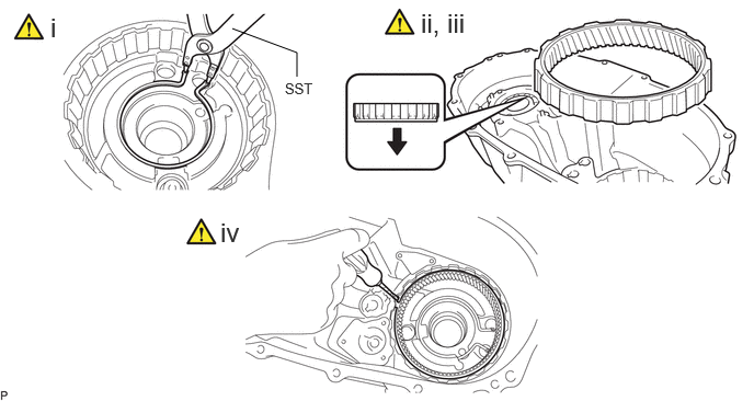
|
|
Front Side | - | - |
Using SST, install the shaft snap ring to the front transfer case.
- SST
-
09350-32014 (09351-32050)
Apply transfer oil to the transfer low planetary ring gear.
Install the transfer low planetary ring gear to the front transfer case.
- NOTICE:
-
Make sure to install the transfer low planetary ring gear in the correct direction.
Using a screwdriver, install the transfer input shaft hole snap ring.
- NOTICE:
-
Check that the transfer input shaft hole snap ring is securely installed.
36111M 20.INSTALL TRANSFER CASE SLOTTED SPRING PIN

| *1 | Transfer Case Plug | *2 | Transfer Case Compression Spring |
| *3 | Transfer Case Slotted Spring Pin | - | - |
Install the transfer case compression spring and transfer case slotted spring pin to the front transfer case.
Apply adhesive to the threads of the transfer case plug.
- Adhesive:
-
Toyota Genuine Adhesive 1344, Three Bond 1344 or equivalent
Install the transfer case plug to the front transfer case.
- Torque:
- 18.6 N*m (190 kgf*cm, 14 ft.*lbf)
21.INSTALL TRANSFER INPUT SHAFT ASSEMBLY
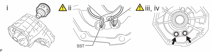
Temporarily install the transfer input shaft assembly to the front transfer case.
Using SST, while expanding the shaft snap ring, install the transfer input shaft assembly to the front transfer case.
- SST
-
09350-32014 (09351-32050)
- NOTICE:
-
Check that the shaft snap ring is securely installed.
Apply adhesive to the threads of the 2 transfer case plugs.
- Adhesive:
-
Toyota Genuine Adhesive 1344, Three Bond 1344 or equivalent
Using a 14 mm hexagon wrench, install the 2 transfer case plugs.
- Torque:
- 37 N*m (377 kgf*cm, 27 ft.*lbf)
36106L 22.INSTALL TRANSFER OIL PUMP ROTOR SET

| *a | Standard Protrusion Height | - | - |
- HINT:
-
There is no need to install this unless the straight pin is replaced.
Using a plastic-faced hammer, tap in 2 new straight pins to the standard protrusion amount.
- Standard Protrusion Height:
-
3.5 to 4.5 mm (0.138 to 0.177 in.)

Apply adhesive to the threads of the straight screw plug.
- Adhesive:
-
Toyota Genuine Adhesive 1344, Three Bond 1344 or equivalent
Using a 6 mm hexagon socket wrench, install the straight screw plug to the oil pump plate sub-assembly.
- Torque:
- 18 N*m (184 kgf*cm, 13 ft.*lbf)
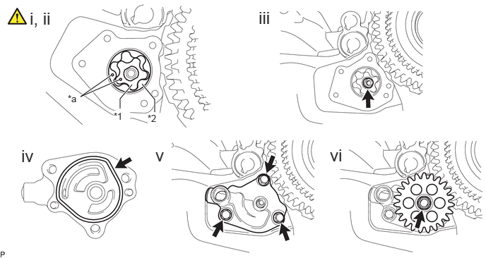
| *1 | Oil Pump Drive Rotor | *2 | Oil Pump Driven Rotor |
| *a | Mark | - | - |
Apply transfer oil to the oil pump drive rotor and oil pump driven rotor.
Install the oil pump drive rotor and oil pump driven rotor with the marks facing the rear transfer case side.
Install the oil pump shaft.
Install a new gasket to the oil pump plate sub-assembly.
Install the oil pump plate sub-assembly with the 3 bolts.
- Torque:
- 8.0 N*m (82 kgf*cm, 71 in.*lbf)
Install the oil pump gear and spacer with the bolt.
- Torque:
- 5.0 N*m (51 kgf*cm, 44 in.*lbf)
33449D 23.INSTALL TRANSFER CASE MAGNET

24.INSTALL TRANSFER OIL SEPARATOR SUB-ASSEMBLY
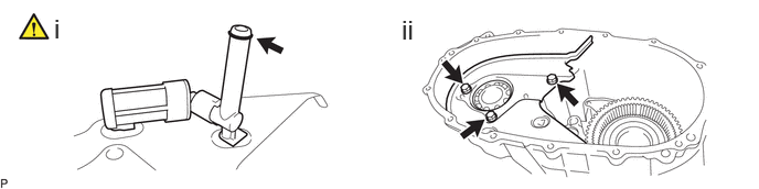
Coat a new O-ring with the transfer oil install it to the transfer oil strainer.
Install the transfer oil separator sub-assembly to the front transfer case with the 3 bolts.
- Torque:
- 17.5 N*m (178 kgf*cm, 13 ft.*lbf)
36231E 25.INSTALL FRONT TRANSFER OUTPUT SHAFT NEEDLE ROLLER BEARING
36112 26.INSTALL REAR TRANSFER CASE
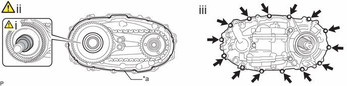
| *a | Seal Packing |
|
Transfer Oil |
Apply transfer oil to the rear transfer output shaft assembly at the points shown in the illustration.
Apply seal packing (Diameter: 1.2 mm (0.0472 in.)) to the rear transfer case as shown in the illustration.
- Seal Packing:
-
Toyota Genuine Seal Packing 1281, Three Bond 1281 or equivalent
Install the rear transfer case to the front transfer case with the 14 bolts.
- Torque:
- 28 N*m (286 kgf*cm, 21 ft.*lbf)
36102J 27.INSTALL TRANSFER COVER TYPE T OIL SEAL
|
|
() |
33309B 28.INSTALL OUTPUT SHAFT COMPANION FLANGE SUB-ASSEMBLY (REAR)
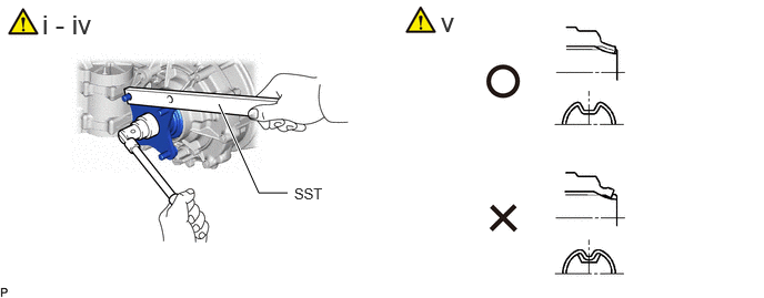
Install a new O-ring to the output shaft companion flange sub-assembly (rear).
Apply transfer oil to the rear transfer output shaft.
Install the output shaft companion flange sub-assembly (rear) onto the rear transfer output shaft.
Using SST, hold the output shaft companion flange sub-assembly (rear) and install a new transfer output shaft nut.
- SST
-
09330-00021
- Torque:
- 111.5 N*m (1137 kgf*cm, 82 ft.*lbf)
Using a chisel and hammer, stake the transfer output shaft nut.
36111B 29.INSTALL TRANSFER CASE OIL SEAL
|
|
() |
33309C 30.INSTALL OUTPUT SHAFT COMPANION FLANGE SUB-ASSEMBLY (FRONT)
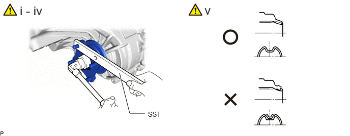
Install a new O-ring to the output shaft companion flange sub-assembly (front).
Apply transfer oil to the transfer driven sprocket.
Install the output shaft companion flange sub-assembly (front) onto the transfer driven sprocket.
Using SST, hold the output shaft companion flange sub-assembly (front) and install a new transfer output shaft nut.
- SST
-
09330-00021
- Torque:
- 111.5 N*m (1137 kgf*cm, 82 ft.*lbf)
Using a chisel and hammer, stake the transfer output shaft nut.
31.INSTALL TRANSFER CASE PLUG
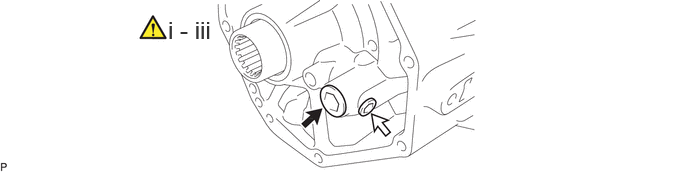
|
|
Transfer Case Plug |
|
No. 2 Transfer Case Plug |
Apply adhesive to the threads of the transfer case plug and No. 2 transfer case plug.
- Adhesive:
-
Toyota Genuine Adhesive 1344, Three Bond 1344 or equivalent
Using a 6 mm hexagon socket wrench, install the No. 2 transfer case plug.
- Torque:
- 22.4 N*m (228 kgf*cm, 17 ft.*lbf)
Using a 14 mm straight hexagon wrench, install the transfer case plug.
- Torque:
- 37 N*m (377 kgf*cm, 27 ft.*lbf)
36115C 32.INSTALL TRANSFER EXTENSION HOUSING TYPE T OIL SEAL

| *a | Depth | - | - |
Using SST and a hammer, tap in a new transfer extension housing type T oil seal to the front transfer case.
- SST
-
09649-17010
09950-70010 (09951-07100)
- Standard Depth:
-
0 to 0.5 mm (0 to 0.0196 in.)
- NOTICE:
-
·
Tap the transfer extension housing type T oil seal evenly so that the transfer extension housing type T oil seal is straight.
·Do not excessively tap the transfer extension housing type T oil seal.
37109A 33.INSTALL PROPELLER SHAFT HEAT INSULATOR BRACKET SUB-ASSEMBLY
- Torque:
- 30 N*m (306 kgf*cm, 22 ft.*lbf)
34.INSTALL FILLER PLUG
- Torque:
- 37 N*m (377 kgf*cm, 27 ft.*lbf)
35.INSTALL DRAIN PLUG
- Torque:
- 37 N*m (377 kgf*cm, 27 ft.*lbf)