REAR SUSPENSION REAR COIL SPRING INSTALLATION
CAUTION / NOTICE / HINT
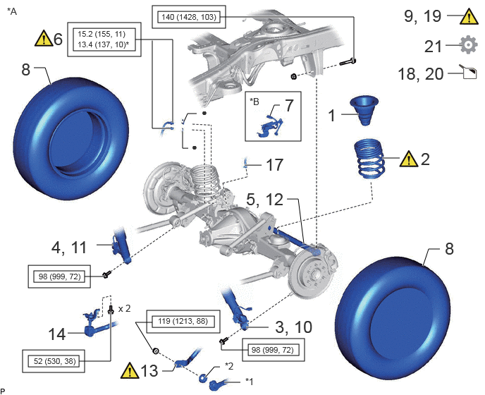
| Procedure | Part Name Code |

|

|

|
|
|---|---|---|---|---|---|
| 1 | HOLLOW SPRING SUB-ASSEMBLY | 48302 | - | - | - |
| 2 | REAR COIL SPRING LH | 48231B | ( ) |
- | - |
| 3 | TEMPORARILY TIGHTEN REAR SHOCK ABSORBER ASSEMBLY LH | 48540 | - | - | - |
| 4 | TEMPORARILY TIGHTEN REAR SHOCK ABSORBER ASSEMBLY RH | 48530 | - | - | - |
| 5 | TEMPORARILY TIGHTEN REAR LATERAL CONTROL ROD ASSEMBLY | 48740 | - | - | - |
| 6 | REAR FLEXIBLE HOSE | - | () |
- | - |
| 7 | REAR HEIGHT CONTROL SENSOR SUB-ASSEMBLY RH | 89407B | - | - | - |
| 8 | REAR WHEEL | - | - | - | - |
| 9 | STABILIZE SUSPENSION | - | () |
- | - |
| 10 | FULLY TIGHTEN REAR SHOCK ABSORBER ASSEMBLY LH | 48540 | - | - | - |
| 11 | FULLY TIGHTEN REAR SHOCK ABSORBER ASSEMBLY RH | 48530 | - | - | - |
| 12 | FULLY TIGHTEN REAR LATERAL CONTROL ROD ASSEMBLY | 48740 | - | - | - |
| 13 | REAR STABILIZER BAR SUB-ASSEMBLY | 48805 | () |
- | - |
| 14 | REAR STABILIZER LINK ASSEMBLY | 48802 | - | - | - |
| 17 | REAR AXLE BREATHER HOSE SUB-ASSEMBLY | 42306 | - | - | - |
| 18 | ADD BRAKE FLUID | - | - | () |
- |
| 19 | CONNECT CABLE TO NEGATIVE BATTERY TERMINAL | - | () |
- | - |
| 20 | BLEED BRAKE LINE | - | - | () |
- |
| 21 | INITIALIZATION AFTER RECONNECTING BATTERY TERMINAL | - | - | - | () |
| *A | w/ Electronic-Kinetic Dynamic Suspension System | *B | w/ Height Control Sensor |
| *1 | REAR STABILIZER CONTROL ARM ASSEMBLY | *2 | LOWER BALL JOINT DUST COVER PROTECTOR |

|
Tightening torque for "Major areas involving basic vehicle performance such as moving/turning/stopping": N*m (kgf*cm, ft.*lbf) | * | For use with a union nut wrench |
| ● | Non-reusable part | - | - |
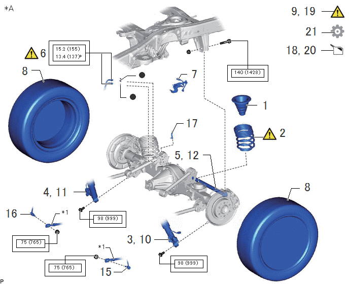
| Procedure | Part Name Code |
|
|
|
|
|---|---|---|---|---|---|
| 1 | HOLLOW SPRING SUB-ASSEMBLY | 48302 | - | - | - |
| 2 | REAR COIL SPRING LH | 48231B | () |
- | - |
| 3 | TEMPORARILY TIGHTEN REAR SHOCK ABSORBER ASSEMBLY LH | 48540 | - | - | - |
| 4 | TEMPORARILY TIGHTEN REAR SHOCK ABSORBER ASSEMBLY RH | 48530 | - | - | - |
| 5 | TEMPORARILY TIGHTEN REAR LATERAL CONTROL ROD ASSEMBLY | 48740 | - | - | - |
| 6 | REAR FLEXIBLE HOSE | - | () |
- | - |
| 7 | REAR HEIGHT CONTROL SENSOR SUB-ASSEMBLY RH | 89407B | - | - | - |
| 8 | REAR WHEEL | - | - | - | - |
| 9 | STABILIZE SUSPENSION | - | () |
- | - |
| 10 | FULLY TIGHTEN REAR SHOCK ABSORBER ASSEMBLY LH | 48540 | - | - | - |
| 11 | FULLY TIGHTEN REAR SHOCK ABSORBER ASSEMBLY RH | 48530 | - | - | - |
| 12 | FULLY TIGHTEN REAR LATERAL CONTROL ROD ASSEMBLY | 48740 | - | - | - |
| 15 | REAR STABILIZER LINK ASSEMBLY LH | 48840A | - | - | - |
| 16 | REAR STABILIZER LINK ASSEMBLY RH | 48830D | - | - | - |
| 17 | REAR AXLE BREATHER HOSE SUB-ASSEMBLY | 42306 | - | - | - |
| 18 | ADD BRAKE FLUID | - | - | () |
- |
| 19 | CONNECT CABLE TO NEGATIVE BATTERY TERMINAL | - | () |
- | - |
| 20 | BLEED BRAKE LINE | - | - | () |
- |
| 21 | INITIALIZATION AFTER RECONNECTING BATTERY TERMINAL | - | - | - | () |
| *A | w/o Electronic-Kinetic Dynamic Suspension System | *B | w/ Height Control Sensor |
| *1 | REAR STABILIZER BAR SUB-ASSEMBLY | - | - |
|
|
Tightening torque for "Major areas involving basic vehicle performance such as moving/turning/stopping": N*m (kgf*cm, ft.*lbf) | * | For use with a union nut wrench |
| ● | Non-reusable part | - | - |
CAUTION / NOTICE / HINT
- HINT:
-
·
Use the same procedure for the RH and LH sides.
·The procedure listed below is for the LH side.
PROCEDURE

 48302 1.INSTALL HOLLOW SPRING SUB-ASSEMBLY
48231B 2.INSTALL REAR COIL SPRING LH
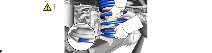
Install the rear coil spring LH.
- HINT:
-
Before installing the rear coil spring LH, check that the coil spring end is in the correct position. If not, reinstall it.
48540 3.TEMPORARILY TIGHTEN REAR SHOCK ABSORBER ASSEMBLY LH
48530 4.TEMPORARILY TIGHTEN REAR SHOCK ABSORBER ASSEMBLY RH
48740 5.TEMPORARILY TIGHTEN REAR LATERAL CONTROL ROD ASSEMBLY
6.CONNECT REAR FLEXIBLE HOSE
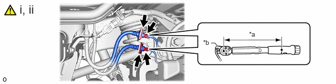
| *a | Torque Wrench Fulcrum Length | *b | Union Nut Wrench |
Install the rear brake tube flexible hose with 2 new clips.
- NOTICE:
-
Install the clip as far as it will go.
Using a union nut wrench, connect the 2 brake lines to the 2 rear flexible hoses while holding the 2 rear flexible hoses with a wrench.
- Torque:
- Specified tightening torque : 15.2 N*m (155 kgf*cm, 11 ft.*lbf)
- NOTICE:
-
·
Do not kink or damage the brake line.
·Do not allow any foreign matter such as dirt or dust to enter the brake line from the connecting parts.
- HINT:
-
·
Calculate the torque wrench reading when changing the fulcrum length of the torque wrench.
Click hereGeneral>INTRODUCTION>REPAIR INSTRUCTION>PRECAUTION
·When using a union nut wrench (fulcrum length of 22 mm (0.866 in.)) + torque wrench (fulcrum length of 162 mm (6.38 in.)):
13.4 N*m (137 kgf*cm, 10 ft.*lbf)
89407B 7.INSTALL REAR HEIGHT CONTROL SENSOR SUB-ASSEMBLY RH (w/ Height Control Sensor)
8.INSTALL REAR WHEEL
9.STABILIZE SUSPENSION
|
|
Click here() |
48540 10.FULLY TIGHTEN REAR SHOCK ABSORBER ASSEMBLY LH
- Torque:
- 98 N*m (999 kgf*cm, 72 ft.*lbf)
48530 11.FULLY TIGHTEN REAR SHOCK ABSORBER ASSEMBLY RH
Use the same procedures described for the LH side.
48740 12.FULLY TIGHTEN REAR LATERAL CONTROL ROD ASSEMBLY
48805 13.CONNECT REAR STABILIZER BAR SUB-ASSEMBLY (w/ Electronic-Kinetic Dynamic Suspension System)
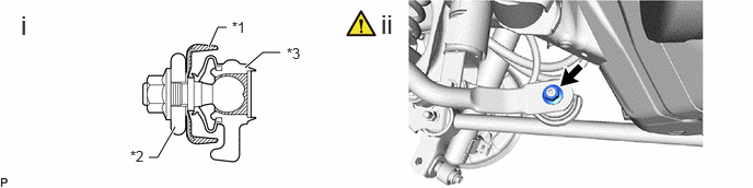
| *1 | Ball Joint Dust Cover Protector | *2 | Rear Stabilizer Link Assembly |
| *3 | Rear Stabilizer Bar Sub-assembly | - | - |
Install the ball joint dust cover protector to the rear stabilizer link assembly.
Connect the rear stabilizer link assembly to the stabilizer bar with the nut.
- Torque:
- 119 N*m (1213 kgf*cm, 88 ft.*lbf)
- HINT:
-
·
If the ball joint turns together with the nut, use a 6 mm hexagon wrench to hold the stud bolt.
·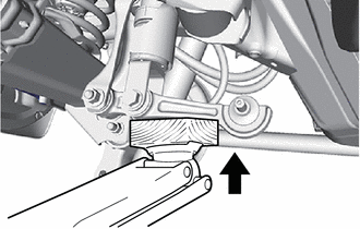
If the rear stabilizer control cylinder extends and it is difficult to temporarily install the stabilizer link to the stabilizer bar, raise the stabilizer control arm with a jack and temporarily install the stabilizer link.
48802 14.CONNECT STABILIZER LINK SUB-ASSEMBLY (w/ Electronic-Kinetic Dynamic Suspension System)
- Torque:
- 52 N*m (530 kgf*cm, 38 ft.*lbf)
48840A 15.CONNECT REAR STABILIZER LINK ASSEMBLY LH (w/o Electronic-Kinetic Dynamic Suspension System)
- Torque:
- 75 N*m (765 kgf*cm, 55 ft.*lbf)
48830D 16.CONNECT REAR STABILIZER LINK ASSEMBLY RH (w/o Electronic-Kinetic Dynamic Suspension System)
Use the same procedures described for the LH side.
42306 17.CONNECT REAR AXLE BREATHER HOSE SUB-ASSEMBLY
18.ADD BRAKE FLUID
19.CONNECT CABLE TO NEGATIVE BATTERY TERMINAL
|
|
Click here() |
20.BLEED BRAKE LINE
21. INITIALIZATION AFTER RECONNECTING BATTERY TERMINAL
Click hereGeneral>SETUP>WHEN DISCONNECTING OR RECONNECTING BATTERY TERMINAL>WORK PROCEDURE
- HINT:
-
When disconnecting and reconnecting the battery, there is an automatic learning function that completes learning when the respective system is used.
-
Click hereGeneral>SETUP>WHEN DISCONNECTING OR RECONNECTING BATTERY TERMINAL>AUTOMATIC LEARNING CHART