REAR SUSPENSION REAR STABILIZER BAR(w/ Electronic-Kinetic Dynamic Suspension System) REMOVAL
CAUTION / NOTICE / HINT
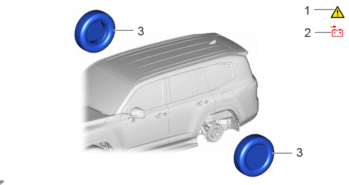
| Procedure | Part Name Code |

|

|

|
|
|---|---|---|---|---|---|
| 1 | PRECAUTION | - | ( ) |
- | - |
| 2 | DISCONNECT CABLE FROM NEGATIVE BATTERY TERMINAL | - | - | - | - |
| 3 | REAR WHEEL | - | - | - | - |
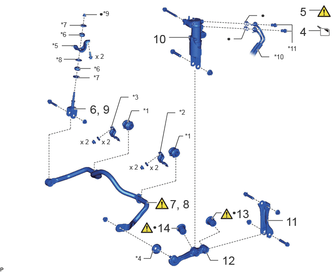
| Procedure | Part Name Code |
|
|
|
|
|---|---|---|---|---|---|
| 4 | DRAIN SUSPENSION FLUID | - | - | () |
- |
| 5 | SUPPORT REAR AXLE HOUSING ASSEMBLY | - | () |
- | - |
| 6 | DISCONNECT STABILIZER LINK SUB-ASSEMBLY | 48802 | - | - | - |
| 7 | DISCONNECT REAR STABILIZER BAR SUB-ASSEMBLY | 48805 | () |
- | - |
| 8 | REMOVE REAR STABILIZER BAR SUB-ASSEMBLY | 48805 | - | - | - |
| 9 | REMOVE STABILIZER LINK SUB-ASSEMBLY | 48802 | - | - | - |
| 10 | REAR STABILIZER CONTROL CYLINDER | 48885 | - | - | - |
| 11 | REAR NO. 2 STABILIZER CONTROL ARM | 488B2 | - | - | - |
| 12 | REAR STABILIZER CONTROL ARM ASSEMBLY | 488B0 | - | - | - |
| 13 | REAR STABILIZER LINK BUSH (for Rear Side) | 48849D | () |
- | - |
| 14 | REAR STABILIZER LINK BUSH (for Front Side) | 48849D | () |
- | - |
| *1 | REAR STABILIZER BUSH | *2 | REAR STABILIZER BAR BRACKET LH |
| *3 | REAR STABILIZER BAR BRACKET RH | *4 | LOWER BALL JOINT DUST COVER PROTECTOR |
| *5 | STABILIZER END BRACKET RH | *6 | REAR STABILIZER CUSHION |
| *7 | REAR NO. 1 STABILIZER BAR CUSHION RETAINER | *8 | REAR NO. 2 STABILIZER BAR CUSHION RETAINER |
| *9 | LOCK NUT | *10 | REAR STABILIZER CONTROL TUBE |
| *11 | UNION BOLT | - | - |
| ● | Non-reusable part | - | - |
CAUTION / NOTICE / HINT
The necessary procedures (adjustment, calibration, initialization, or registration) that must be performed after parts are removed, installed, or replaced during the rear stabilizer bar removal/installation are shown below.
- Necessary Procedure After Parts Removed/Installed/Replaced:
-
Replacement Part or Procedure Necessary Procedures Effects/Inoperative when not Performed Link Suspension, tires, etc. Rear television camera assembly optical axis (Back camera position setting) Parking assist monitor system ( )·Parking assist ECU initialization
·Adjust steering angle
·Rear television camera view adjustment (for Rear camera detection system)
Panoramic view monitor system ( )Replacement of the rear height control sensor sub-assembly LH, removal and reinstallation of the rear height control sensor sub-assembly LH, replacement of the suspension, etc. have been performed. Perform headlight ECU sub-assembly LH initialization Automatic headlight beam level control system ( )Disconnect cable from negative auxiliary battery terminal Memorize steering angle neutral point Parking assist monitor system ( )Multi-terrain monitor system ( )Panoramic view monitor system ( )
- HINT:
-
When the cable is disconnected/reconnected to the auxiliary battery terminal, systems temporarily stop operating. However, each system has a function that completes learning the first time the system is used.
-
·
Learning completes when vehicle is driven
Effect/Inoperative Function When Necessary Procedures are not Performed Necessary Procedures Link Stop and start system Drive the vehicle until stop and start control is permitted (approximately 5 to 60 minutes). ( )Lighting system (EXT) Cornering lights Drive the vehicle straight ahead at 35 km/h (22 mph) or more for 5 seconds or more. ( )Pre-collision system Lane tracing assist system Lane departure alert system Adaptive high beam system
·Learning completes when vehicle is operated normally
Effect/Inoperative Function When Necessary Procedures are not Performed Necessary Procedures Link Power back door system Fully close the back door by hand.
- HINT:
-
Initialization is not necessary if the above procedures are performed while the back door is closed.
( )Air conditioning system After the ignition switch is turned to ON, the servo motor and expansion valve standard position is recognized. -
PROCEDURE

 1. PRECAUTION
|
|
|
2.DISCONNECT CABLE FROM NEGATIVE BATTERY TERMINAL
3.REMOVE REAR WHEEL
4.DRAIN SUSPENSION FLUID
|
|
Click here() |
5.SUPPORT REAR AXLE HOUSING ASSEMBLY
|
|
Click here() |
48802 6.DISCONNECT STABILIZER LINK SUB-ASSEMBLY
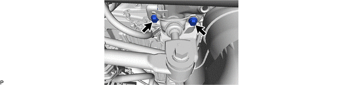
48805 7.DISCONNECT REAR STABILIZER BAR SUB-ASSEMBLY
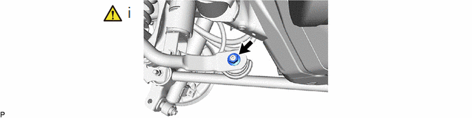
Remove the nut and disconnect the rear stabilizer bar sub-assembly.
- NOTICE:
-
Do not lose the lower ball joint dust cover protector.
- HINT:
-
If the ball joint turns together with the nut, use a 6 mm hexagon wrench to hold the stud.
48805 8.REMOVE REAR STABILIZER BAR SUB-ASSEMBLY
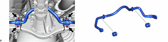
48802 9.REMOVE STABILIZER LINK SUB-ASSEMBLY
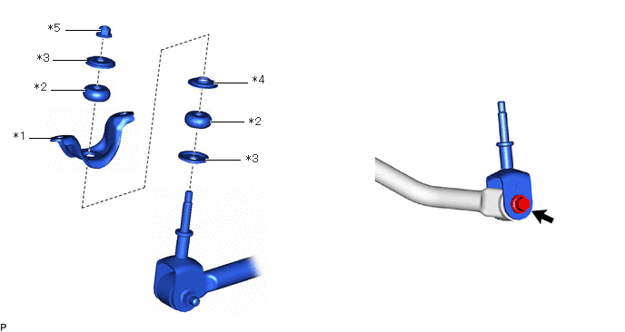
| *1 | Stabilizer End Bracket RH | *2 | Rear Stabilizer Cushion |
| *3 | Rear No. 1 Stabilizer Bar Cushion Retainer | *4 | Rear No. 2 Stabilizer Bar Cushion Retainer |
| *5 | Lock Nut | - | - |
48885 10.REMOVE REAR STABILIZER CONTROL CYLINDER
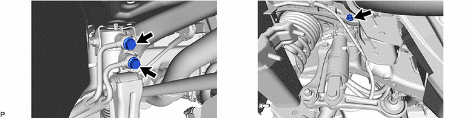
488B2 11.REMOVE REAR NO. 2 STABILIZER CONTROL ARM
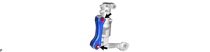
488B0 12.REMOVE REAR STABILIZER CONTROL ARM ASSEMBLY
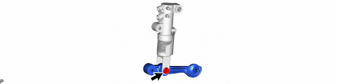
48849D 13.REMOVE REAR STABILIZER LINK BUSH (for Rear Side)
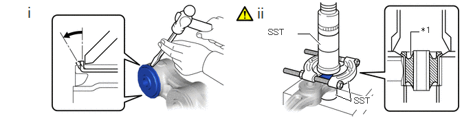
| *1 | Rear Stabilizer Link Bush (Rear Side) | - | - |
Using a hammer and chisel, strike and bend the entire flange of the rear stabilizer link bush (rear side) as shown in the illustration.
Using SST and a press, press out the rear stabilizer link bush (rear side).
- SST
-
09613-26010
09710-22021 (09710-01031)
09950-00020
48849D 14.REMOVE REAR STABILIZER LINK BUSH (for Front Side)
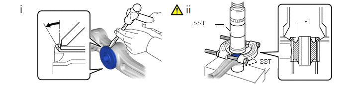
| *1 | Rear Stabilizer Link Bush (Front Side) | - | - |
Using a hammer and chisel, strike and bend the entire flange of the rear stabilizer link bush (front side) as shown in the illustration.
Using SST and a press, press out the rear stabilizer link bush (front side).
- SST
-
09613-26010
09710-22021 (09710-01031)
09950-00020