V35A-FTS INTAKE / EXHAUST INTAKE MANIFOLD INSTALLATION
CAUTION / NOTICE / HINT
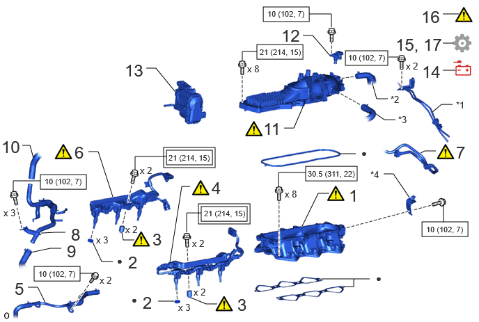
| Procedure | Part Name Code |

|

|

|
|
|---|---|---|---|---|---|
| 1 | INTAKE MANIFOLD | 17111 | ( ) |
- | - |
| 2 | INJECTOR VIBRATION INSULATOR | 23291 | - | - | - |
| 3 | FUEL DELIVERY SPACER | 23891 | () |
- | - |
| 4 | NO. 1 FUEL DELIVERY PIPE SUB-ASSEMBLY LH | 23808A | () |
- | - |
| 5 | NO. 6 WATER BY-PASS PIPE | 1628A | - | - | - |
| 6 | NO. 1 FUEL DELIVERY PIPE SUB-ASSEMBLY RH | 23807L | () |
- | - |
| 7 | FUEL TUBE SUB-ASSEMBLY | 23910A | () |
- | - |
| 8 | NO. 5 WATER BY-PASS PIPE | 16289 | - | - | - |
| 9 | NO. 14 WATER BY-PASS HOSE | 16296 | - | - | - |
| 10 | WATER HOSE SUB-ASSEMBLY | 87209 | - | - | - |
| 11 | INTAKE AIR SURGE TANK ASSEMBLY | 17190 | () |
- | - |
| 12 | NO. 3 TURBO PRESSURE SENSOR | 89421Q | - | - | - |
| 13 | THROTTLE WITH THROTTLE POSITION SENSOR BODY ASSEMBLY | 22030 | - | - | - |
| 14 | CONNECT CABLE TO NEGATIVE BATTERY TERMINAL | - | - | - | - |
| 15 | INITIALIZATION AFTER RECONNECTING BATTERY TERMINAL | - | - | - | () |
| 16 | INSPECT FOR FUEL LEAK | - | () |
- | - |
| 17 | PERFORM INITIALIZATION | - | - | - | () |
| *1 | NO. 3 TURBO WATER PIPE SUB-ASSEMBLY | *2 | VENTILATION HOSE |
| *3 | NO. 3 FUEL VAPOR FEED HOSE | *4 | FUEL HOSE BRACKET |

|
Tightening torque for "Major areas involving basic vehicle performance such as moving/turning/stopping": N*m (kgf*cm, ft.*lbf) |

|
N*m (kgf*cm, ft.*lbf): Specified torque |
| ● | Non-reusable part | - | - |
CAUTION / NOTICE / HINT
- NOTICE:
-
This procedure includes the installation of small-head bolts. Refer to Small-Head Bolts of Basic Repair Hint to identify the small-head bolts.
-
Click hereGeneral>INTRODUCTION>REPAIR INSTRUCTION>PRECAUTION
PROCEDURE

 17111 1.INSTALL INTAKE MANIFOLD
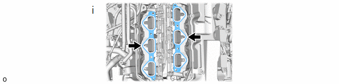
Set 2 new gaskets on cylinder head as shown in the illustration.
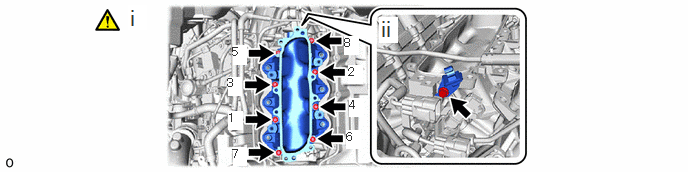
Install the intake manifold with the 8 bolts in the order shown in the illustration.
- Torque:
- 30.5 N*m (311 kgf*cm, 22 ft.*lbf)
Install the fuel hose bracket to the intake manifold with the bolt.
- Torque:
- 10 N*m (102 kgf*cm, 7 ft.*lbf)
23291 2.INSTALL INJECTOR VIBRATION INSULATOR
23891 3.INSTALL FUEL DELIVERY SPACER
|
|
Click here() |
23808A 4.INSTALL NO. 1 FUEL DELIVERY PIPE SUB-ASSEMBLY LH
|
|
Click here() |
1628A 5.CONNECT NO. 6 WATER BY-PASS PIPE
23807L 6.INSTALL NO. 1 FUEL DELIVERY PIPE SUB-ASSEMBLY RH
|
|
Click here() |
23910A 7.CONNECT FUEL TUBE SUB-ASSEMBLY
|
|
Click here() |
16289 8.INSTALL NO. 5 WATER BY-PASS PIPE
1629A 9.CONNECT NO. 14 WATER BY-PASS HOSE
87209 10.CONNECT WATER HOSE SUB-ASSEMBLY
17190 11.INSTALL INTAKE AIR SURGE TANK ASSEMBLY
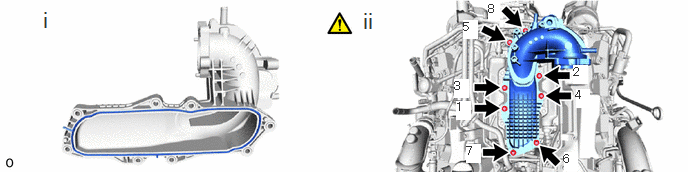
Install a new gasket to the intake air surge tank assembly as shown in the illustration.
Install the intake air surge tank assembly with the 8 bolts in the order shown in the illustration.
- Torque:
- 21 N*m (214 kgf*cm, 15 ft.*lbf)
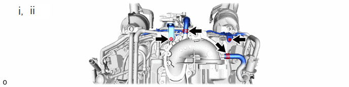
Connect the No. 3 turbo water pipe sub-assembly with the 2 bolts.
- Torque:
- 10 N*m (102 kgf*cm, 7 ft.*lbf)
Connect the 2 hoses to the intake air surge tank assembly.
89421Q 12.INSTALL NO. 3 TURBO PRESSURE SENSOR
22030 13.INSTALL THROTTLE WITH THROTTLE POSITION SENSOR BODY ASSEMBLY
14.CONNECT CABLE TO NEGATIVE BATTERY TERMINAL
15. INITIALIZATION AFTER RECONNECTING BATTERY TERMINAL
Click hereGeneral>SETUP>WHEN DISCONNECTING OR RECONNECTING BATTERY TERMINAL>WORK PROCEDURE
- HINT:
-
When disconnecting and reconnecting the battery, there is an automatic learning function that completes learning when the respective system is used.
-
Click hereGeneral>SETUP>WHEN DISCONNECTING OR RECONNECTING BATTERY TERMINAL>AUTOMATIC LEARNING CHART
16.INSPECT FOR FUEL LEAK
17.PERFORM INITIALIZATION