V35A-FTS FUEL FUEL INJECTOR(for Port Injection) INSTALLATION
CAUTION / NOTICE / HINT
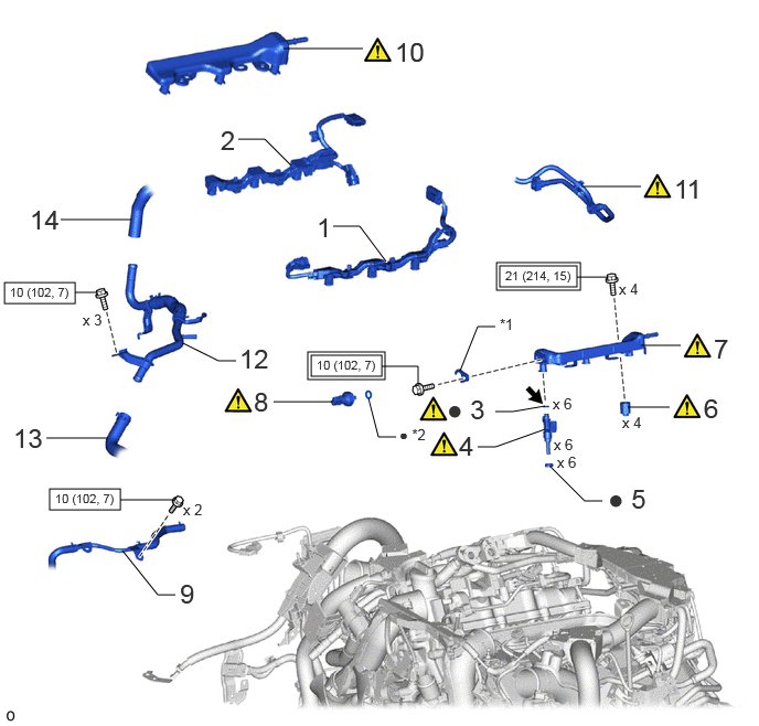
| Procedure | Part Name Code |

|

|

|
|
|---|---|---|---|---|---|
| 1 | NO. 8 ENGINE WIRE | 82128A | - | - | - |
| 2 | NO. 7 ENGINE WIRE | 82127D | - | - | - |
| 3 | FUEL INJECTOR O-RING | 23250G | ( ) |
- | - |
| 4 | PORT FUEL INJECTOR ASSEMBLY | 23250F | () |
- | - |
| 5 | INJECTOR VIBRATION INSULATOR | 23291 | - | - | - |
| 6 | FUEL DELIVERY SPACER | 23891 | () |
- | - |
| 7 | NO. 1 FUEL DELIVERY PIPE SUB-ASSEMBLY LH | 23808A | () |
- | - |
| 8 | NO. 2 FUEL PRESSURE SENSOR | 89458H | () |
- | - |
| 9 | NO. 6 WATER BY-PASS PIPE | 1628A | - | - | - |
| 10 | NO. 1 FUEL DELIVERY PIPE SUB-ASSEMBLY RH | 23807L | () |
- | - |
| 11 | FUEL TUBE SUB-ASSEMBLY | 23910A | () |
- | - |
| 12 | NO. 5 WATER BY-PASS PIPE | 16289 | - | - | - |
| 13 | NO. 14 WATER BY-PASS HOSE | 1629A | - | - | - |
| 14 | WATER HOSE SUB-ASSEMBLY | 87209 | - | - | - |
| *1 | NO. 2 FUEL PRESSURE SENSOR HOLDER | *2 | O-RING |

|
Tightening torque for "Major areas involving basic vehicle performance such as moving/turning/stopping": N*m (kgf*cm, ft.*lbf) |

|
N*m (kgf*cm, ft.*lbf): Specified torque |
| ● | Non-reusable part |

|
Gasoline |
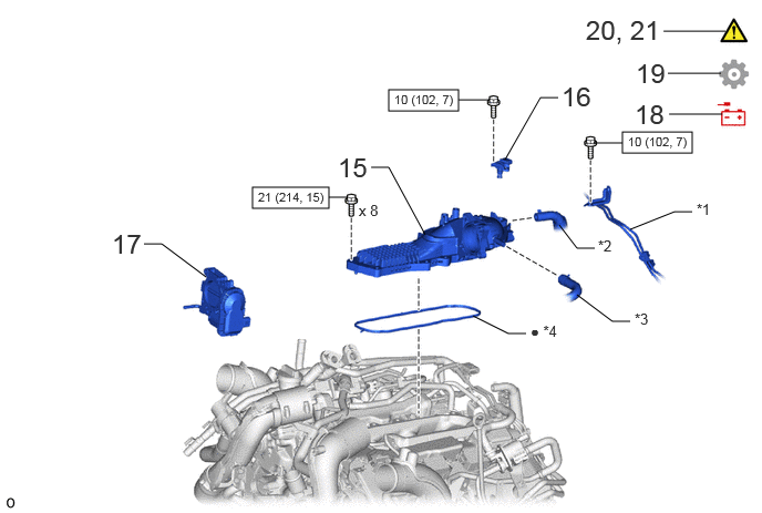
| Procedure | Part Name Code |
|
|
|
|
|---|---|---|---|---|---|
| 15 | INTAKE AIR SURGE TANK ASSEMBLY | 17190 | - | - | - |
| 16 | NO. 3 TURBO PRESSURE SENSOR | 89421Q | - | - | - |
| 17 | THROTTLE WITH THROTTLE POSITION SENSOR BODY ASSEMBLY | 22030 | - | - | - |
| 18 | CONNECT CABLE TO NEGATIVE BATTERY TERMINAL | - | - | - | - |
| 19 | INITIALIZATION AFTER RECONNECTING BATTERY TERMINAL | - | - | - | () |
| 20 | INSPECT FOR FUEL LEAK | - | () |
- | - |
| 21 | PERFORM INITIALIZATION | - | () |
- | - |
| *1 | NO. 3 TURBO WATER PIPE SUB-ASSEMBLY | *2 | VENTILATION HOSE |
| *3 | NO. 3 VAPOR FEED HOSE | *4 | GASKET |
|
|
N*m (kgf*cm, ft.*lbf): Specified torque | ● | Non-reusable part |
CAUTION / NOTICE / HINT
- NOTICE:
-
This procedure includes the installation of small-head bolts. Refer to Small-Head Bolts of Basic Repair Hint to identify the small-head bolts.
-
Click hereGeneral>INTRODUCTION>REPAIR INSTRUCTION>PRECAUTION
- HINT:
-
Perform "Inspection After Repair" after replacing a port fuel injector assembly.
-
Click hereEngine / Hybrid System>V35A-FTS (ENGINE CONTROL)>SFI SYSTEM>INITIALIZATION
PROCEDURE

 82128A 1.INSTALL NO. 8 ENGINE WIRE
82127D 2.INSTALL NO. 7 ENGINE WIRE
23250G 3.INSTALL FUEL INJECTOR O-RING
|
|
|
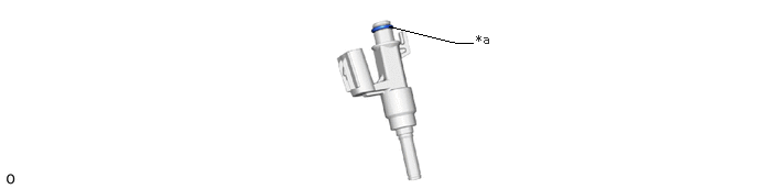
| *a | Apply gasoline | - | - |
23250F 4.INSTALL PORT FUEL INJECTOR ASSEMBLY
|
|
|
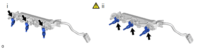
Connect the 3 connectors to the 3 port fuel injector assemblies.
Install the 3 port fuel injector assemblies to the No. 1 fuel delivery pipe sub-assembly LH.
- NOTICE:
-
·
Check that the port fuel injector assembly installation holes of the No. 1 fuel delivery pipe sub-assembly LH are not damaged and are free of foreign matter.
·Make sure that the O-ring is not damaged, twisted or moved out of place when installing the port fuel injector assembly.
·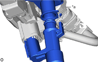 2.042,0.479 2.365,0.25 2.365,0.25 2.49,0.25 true 2.188,0.917 2.771,0.917 true 2.521,0.156 2.75,0.323 0.229,0.167 10 true *a 2.792,0.823 3.021,0.99 0.229,0.167 10 true *b
*a Groove *b Protrusion
Align the protrusion of the port fuel injector assembly to the groove of the No. 1 fuel delivery pipe sub-assembly LH.
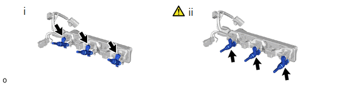
Connect the 3 connectors to the 3 port fuel injector assemblies.
Install the 3 port fuel injector assemblies to the No. 1 fuel delivery pipe sub-assembly RH.
- NOTICE:
-
·
Check that the port fuel injector assembly installation holes of the No. 1 fuel delivery pipe sub-assembly RH are not damaged and are free of foreign matter.
·Make sure that the O-ring is not damaged, twisted or moved out of place when installing the port fuel injector assembly.
·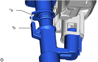 0.656,0.99 1.104,0.99 true 1.167,0.542 0.74,0.365 0.74,0.365 0.563,0.365 true 0.323,0.271 0.552,0.438 0.229,0.167 10 true *a 0.417,0.896 0.646,1.063 0.229,0.167 10 true *b
*a Groove *b Protrusion
Align the protrusion of the port fuel injector assembly to the groove of the No. 1 fuel delivery pipe sub-assembly RH.
23291 5.INSTALL INJECTOR VIBRATION INSULATOR
23891 6.INSTALL FUEL DELIVERY SPACER
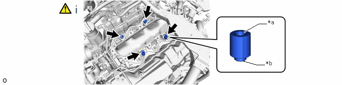
| *a | Fuel Delivery Sub-assembly Side | *b | Intake Manifold Side |
Install the 4 fuel delivery spacers to the intake manifold.
- NOTICE:
-
Install the fuel delivery spacer in the correct direction.
23808A 7.INSTALL NO. 1 FUEL DELIVERY PIPE SUB-ASSEMBLY LH
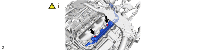
Install the No. 1 fuel delivery pipe sub-assembly LH to the intake manifold with the 2 bolts.
- Torque:
- 21 N*m (214 kgf*cm, 15 ft.*lbf)
- NOTICE:
-
If a port fuel injector assembly is dropped or the tip of the port fuel injector assembly is struck, replace it with a new one.
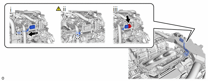
Attach the clamp and connect the No. 8 engine wire to the connector holder.
Attach the claw and close the cover of the connector holder.
Connect the connector to the No. 8 engine wire.
89458H 8.INSTALL NO. 2 FUEL PRESSURE SENSOR
1628A 9.CONNECT NO. 6 WATER BY-PASS PIPE
23807L 10.INSTALL NO. 1 FUEL DELIVERY PIPE SUB-ASSEMBLY RH
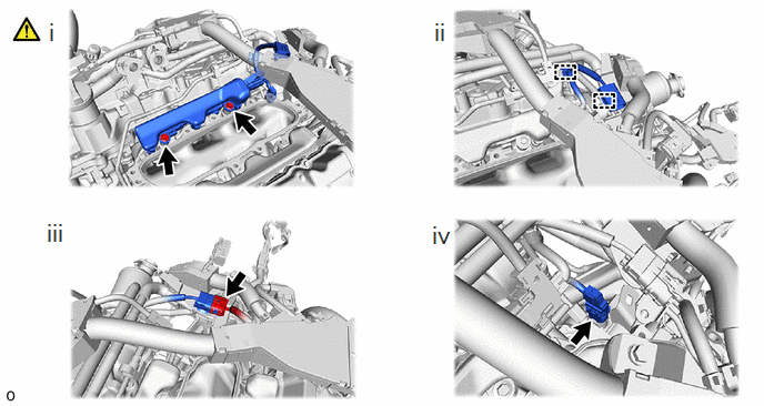
Install the No. 1 fuel delivery pipe sub-assembly RH to the intake manifold with the 2 bolts.
- Torque:
- 21 N*m (214 kgf*cm, 15 ft.*lbf)
- NOTICE:
-
If a port fuel injector assembly is dropped or the tip of the port fuel injector assembly is struck, replace it with a new one.
Attach the 2 clamps and connect the No. 7 engine wire to the wire harness clamp bracket and cylinder head cover sub-assembly RH.
Connect the connector to the No. 7 engine wire.
Connect the connector to the fuel pressure sensor.
23910A 11.CONNECT FUEL TUBE SUB-ASSEMBLY
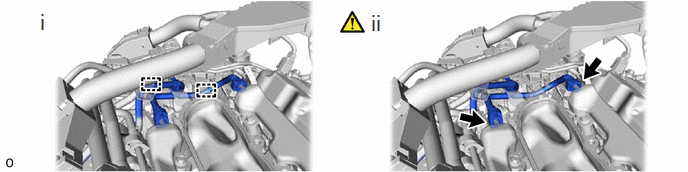
Connect the fuel tube sub-assembly to the 2 fuel hose clamps.
Connect the fuel tube sub-assembly to the No. 1 fuel delivery pipe sub-assembly RH and No. 1 fuel delivery pipe sub-assembly LH.
Click hereEngine / Hybrid System>V35A-FTS (FUEL)>FUEL SYSTEM>PRECAUTION
16289 12.INSTALL NO. 5 WATER BY-PASS PIPE
- Torque:
- 10 N*m (102 kgf*cm, 7 ft.*lbf)
1629A 13.CONNECT NO. 14 WATER BY-PASS HOSE
87209 14.CONNECT WATER HOSE SUB-ASSEMBLY
17190 15.INSTALL INTAKE AIR SURGE TANK ASSEMBLY
89421Q 16.INSTALL NO. 3 TURBO PRESSURE SENSOR
22030 17.INSTALL THROTTLE WITH THROTTLE POSITION SENSOR BODY ASSEMBLY
18.CONNECT CABLE TO NEGATIVE BATTERY TERMINAL
19. INITIALIZATION AFTER RECONNECTING BATTERY TERMINAL
Click hereGeneral>SETUP>WHEN DISCONNECTING OR RECONNECTING BATTERY TERMINAL>WORK PROCEDURE
- HINT:
-
When disconnecting and reconnecting the battery, there is an automatic learning function that completes learning when the respective system is used.
-
Click hereGeneral>SETUP>WHEN DISCONNECTING OR RECONNECTING BATTERY TERMINAL>AUTOMATIC LEARNING CHART
20.INSPECT FOR FUEL LEAK
21.PERFORM INITIALIZATION
Perform "Inspection After Repair" after replacing a port fuel injector assembly.
Click hereEngine / Hybrid System>V35A-FTS (ENGINE CONTROL)>SFI SYSTEM>INITIALIZATION