Home › Engine / Hybrid System › 1GR-FE (COOLING) › WATER PUMP
RM38G0E _51 Engine / Hybrid System _101532 1GR-FE COOLING _0470522 WATER PUMP A

1GR-FE COOLING  WATER PUMP  INSTALLATION  


CAUTION / NOTICE / HINT
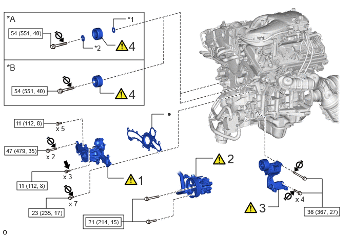
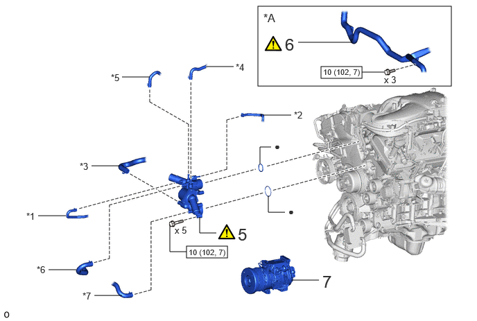
COMPONENTS (INSTALLATION)
A488716N01
0.083,0.25 2.927,2.146 2.844,1.896 0.24,1.76 0.958,1.938 0.719,0.177 0.177,0.583 0.865,0.781 0.688,0.198 0.292,2.427 0.885,2.594 0.594,0.167 0.344,3.698 0.958,3.865 0.615,0.167 0.583,4.24 1.302,4.417 0.719,0.177 0.094,2.979 0.76,3.156 0.667,0.177 1.74,4.427 2.458,4.604 0.719,0.177 6.177,4.219 6.896,4.396 0.719,0.177 1.688,4.375 2.51,4.656 0.823,0.281 0.083,1.219 2.927,1.219 false 3.979,3.604 3.979,3.219 3.979,3.219 4.323,3.219 false 2.031,1.74 2.031,1.896 2.031,1.896 2.323,1.896 false 3.083,2.615 3.083,2.323 3.083,2.323 3.333,2.323 false 5.448,4.208 5.656,4.208 5.656,4.208 5.656,3.844 false 2.302,0.552 2.302,0.385 2.302,0.385 2.552,0.385 false 1.688,0.823 1.688,0.979 1.688,0.979 1.885,0.979 false 2.052,0.75 2.177,0.917 2.177,0.917 2.344,0.917 false 0.865,0.677 1.031,0.677 1.031,0.677 1.031,0.927 false 2.188,3.375 2.188,3.625 2.188,3.625 2.51,3.625 false 0.885,2.51 1.135,2.51 false 0.646,3.698 0.646,3.49 0.646,3.49 1.333,3.49 false 2.688,4.51 2.688,4.052 2.688,4.052 2.938,4.052 false 6.208,3.635 6.542,3.635 6.542,3.635 6.542,4.219 false 1.396,4.031 0.938,4.031 0.938,4.031 0.938,4.24 false 2.469,4.51 2.969,4.51 false 6.125,3.927 6.542,3.927 false 0.958,1.854 1.177,1.854 false 0.76,3.063 0.938,3.063 false 0.135,0.281 0.385,0.49 0.25,0.208 12 false *A 0.135,1.271 0.385,1.479 0.25,0.208 12 false *B 6,3.969 6.25,4.177 0.25,0.208 10 false x 4 1.396,4.063 1.646,4.271 0.25,0.208 10 false x 7 1.281,3.51 1.531,3.719 0.25,0.208 10 false x 3 0.938,3.104 1.188,3.313 0.25,0.208 10 false x 2 1.135,2.531 1.385,2.74 0.25,0.208 10 false x 5 2.615,1.771 2.885,2.063 0.271,0.292 18 false 4 2.615,0.792 2.885,1.083 0.271,0.292 18 false 4 5.26,4.083 5.531,4.375 0.271,0.292 18 false 3 4.615,3.083 4.885,3.375 0.271,0.292 18 false 2 2.792,3.521 3.063,3.813 0.271,0.292 18 false 1 3.396,2.229 3.573,2.417 0.177,0.188 10 false ● 1.917,0.896 2.167,1.104 0.25,0.208 10 false *2 2.594,0.313 2.792,0.49 0.198,0.177 10 false *1 0.292,1.781 0.948,1.958 0.656,0.177 8 false 54 (551, 40) 0.219,0.604 0.875,0.781 0.656,0.177 8 false 54 (551, 40) 0.313,2.438 0.917,2.615 0.604,0.177 8 false 11 (112, 8) 1.792,4.448 2.542,4.625 0.75,0.177 8 false 21 (214, 15) 0.375,3.708 0.979,3.885 0.604,0.177 8 false 11 (112, 8) 0.125,3 0.875,3.177 0.75,0.177 8 false 47 (479, 35) 0.646,4.26 1.396,4.438 0.75,0.177 8 false 23 (235, 17) 6.24,4.24 6.99,4.417 0.75,0.177 8 false 36 (367, 27)

Procedure Part Name Code
Z101186

Z101188

Z101187

1 ENGINE WATER PUMP ASSEMBLY 16100 (Click here) - -
2 VANE PUMP ASSEMBLY 44310 (Click here) - -
3 V-RIBBED BELT TENSIONER ASSEMBLY 16620 (Click here) - -
4 NO. 2 IDLER PULLEY SUB-ASSEMBLY 16604 (Click here) - -

*A for Separate Type *B for Integrated Type
*1 IDLER PULLEY COVER PLATE *2 NO. 2 IDLER PULLEY COVER PLATE
V111893

Tightening torque for "Major areas involving basic vehicle performance such as moving/turning/stopping": N*m (kgf*cm, ft.*lbf)
V100146

N*m (kgf*cm, ft.*lbf): Specified torque
● Non-reusable part
V100135

Adhesive 1344
V103638

Do not apply lubricants to the threads parts - -

A488718N02
2.802,3.698 3.417,3.875 0.615,0.177 4.823,1 5.438,1.177 0.615,0.177 3.875,0.094 6.781,1.292 2.906,1.198 4.479,0.635 5.292,0.635 false 3.958,1.729 4.375,1.729 false 3.094,1 3.51,1 true 1.833,1.156 2.25,1.156 false 1.375,2.49 1.792,2.49 false 0.573,3.24 0.99,3.24 false 0.729,4.052 1.146,4.052 false 1.417,4.438 1.833,4.438 false 4.375,4.208 4.792,4.208 false 3.906,2.458 3.906,2.208 3.906,2.208 4.073,2.208 false 3,3.26 3,3.5 3,3.5 3.25,3.5 false 4.031,2.938 4.031,3.188 4.031,3.188 4.281,3.188 false 2.552,3.375 2.552,3.781 2.552,3.781 2.802,3.781 false 5.438,1.083 5.771,1.083 false 4.844,4.083 5.125,4.375 0.281,0.292 18 false 7 3.573,3.375 3.854,3.667 0.281,0.292 18 false 5 4.281,0.521 4.563,0.813 0.281,0.292 18 false 6 3.542,0.927 3.854,1.125 0.313,0.198 10 false *4 4.417,1.646 4.729,1.844 0.313,0.198 10 false *2 1.667,1.083 1.979,1.281 0.313,0.198 10 false *5 1.198,2.417 1.51,2.615 0.313,0.198 10 false *3 0.396,3.167 0.708,3.365 0.313,0.198 10 false *1 0.552,3.969 0.865,4.167 0.313,0.198 10 false *6 1.24,4.365 1.552,4.563 0.313,0.198 10 false *7 4.333,3.094 4.49,3.281 0.156,0.188 10 false ● 4.125,2.115 4.281,2.302 0.156,0.188 10 false ● 2.625,3.375 2.885,3.573 0.26,0.198 10 false x 5 5.771,1.115 6.031,1.313 0.26,0.198 10 false x 3 2.833,3.719 3.448,3.875 0.615,0.156 8 false 10 (102, 7) 4.854,1.01 5.469,1.167 0.615,0.156 8 false 10 (102, 7) 3.958,0.167 4.292,0.354 0.333,0.188 12 false *A

Procedure Part Name Code
Z101186

Z101188

Z101187

5 WATER INLET ASSEMBLY - (Click here) - -
6 AIR TUBE ASSEMBLY 17360G (Click here) - -
7 COMPRESSOR ASSEMBLY WITH MAGNET CLUTCH 88310E - - -

*A w/ Secondary Air Injection System - -
*1 NO. 1 WATER BY-PASS HOSE *2 NO. 2 WATER BY-PASS HOSE
*3 NO. 3 WATER BY-PASS HOSE *4 NO. 4 WATER BY-PASS HOSE
*5 NO. 5 WATER BY-PASS HOSE *6 NO. 6 WATER BY-PASS HOSE
*7 NO. 7 WATER BY-PASS HOSE - -
V100146

N*m (kgf*cm, ft.*lbf): Specified torque ● Non-reusable part

PROCEDURE

Hide 16100 1.INSTALL ENGINE WATER PUMP ASSEMBLY
a.
A488714C01
1.906,0.115 2.188,0.396 0.281,0.281 18 false i
V100135

Bolt A
V100136

Bolt B
V100137

Bolt C
V100138

Bolt D


i.

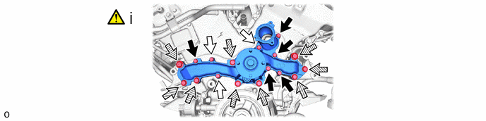
Install a new gasket and the engine water pump assembly to the timing chain cover sub-assembly with the 17 bolts.

Adhesive:

Toyota Genuine Adhesive 1344, Three Bond 1344 or equivalent


Torque:
for bolt A and B : 11 N*m (112 kgf*cm, 8 ft.*lbf)
for bolt C : 23 N*m (235 kgf*cm, 17 ft.*lbf)
for bolt D : 47 N*m (479 kgf*cm, 35 ft.*lbf)

NOTICE:
·

Make sure that there is no oil on the threads of the bolts C and D.

·

Do not reuse the gasket.


Hide 44310 2.CONNECT VANE PUMP ASSEMBLY

a.
A489710C01
0.552,0.063 0.833,0.417 0.281,0.354 18 false i 3.615,0.063 4.229,0.396 0.615,0.333 18 false ii, iii 2.021,0.417 2.177,0.615 0.156,0.198 10 true A 1.948,1.24 2.104,1.438 0.156,0.198 10 true B

i.

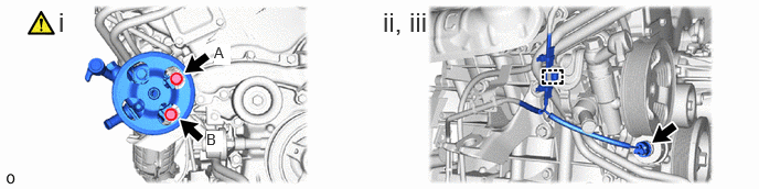
Connect the vane pump assembly with the 2 bolts.

Torque:
21 N*m (214 kgf*cm, 15 ft.*lbf)

NOTICE:

Tighten the bolts in the following sequence: Temporarily install in the order of A to B and fully tighten in the order of A to B.


ii.

Attach the clamp.


iii.

Connect the connector.


Hide 16620 3.INSTALL V-RIBBED BELT TENSIONER ASSEMBLY

Z101186

Click here(Click here)

Hide 16604 4.INSTALL NO. 2 IDLER PULLEY SUB-ASSEMBLY

Z101186

NOTICE:

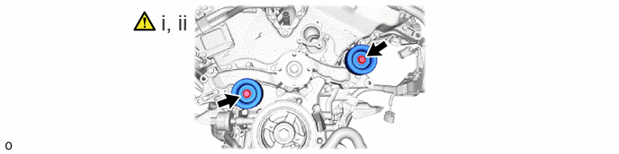
Make sure that there is no oil on the bolt threads.


a.
A489709C01
1.865,0.115 2.281,0.396 0.417,0.281 18 false i, ii

i.

for Separate Type:

1. Install the 2 bolts, 2 idler pulley cover plates, 2 No. 2 idler pulley sub-assemblies and 2 No. 2 idler pulley cover plates.

Torque:
54 N*m (551 kgf*cm, 40 ft.*lbf)


ii.

for Integrated Type:

1. Install the 2 bolts and 2 No. 2 idler pulley sub-assemblies.

Torque:
54 N*m (551 kgf*cm, 40 ft.*lbf)


Hide 5.INSTALL WATER INLET ASSEMBLY

a.
A488709C01
0.24,0.063 0.708,0.365 0.469,0.302 18 false i, ii 3.448,0.042 4.042,0.344 0.594,0.302 18 false iii, iv

i.

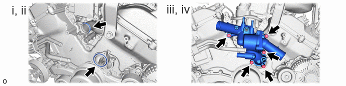
Install a new O-ring to the water outlet pipe.


ii.

Install a new gasket to the engine water pump assembly.


iii.

Apply soapy water to the O-ring of the water outlet pipe.


iv.

Install the water inlet assembly with the 5 bolts.

Torque:
10 N*m (102 kgf*cm, 7 ft.*lbf)


b.
A488710C01
5.635,1.563 5.573,1.906 5.573,1.906 5.396,1.906 true 3.781,0.99 3.99,0.99 3.99,0.99 4.208,0.646 true 1.76,1.604 1.875,1.406 1.875,1.406 2.042,1.406 true 1.792,3.427 1.958,3.427 1.958,3.427 1.958,3.094 true 1.417,2.073 1.177,2.073 1.177,2.073 1.031,1.792 true 1.563,3.427 1.323,3.427 1.323,3.427 1.042,3.104 true 3.552,0.979 3.385,0.979 3.385,0.979 3.229,0.5 true 1.635,3.333 1.844,3.563 0.208,0.229 10 false *a 2.063,1.313 2.271,1.542 0.208,0.229 10 false *a 3.615,0.896 3.823,1.125 0.208,0.229 10 false *a 5.229,1.823 5.438,2.052 0.208,0.229 10 false *a 2.063,2.979 2.271,3.208 0.208,0.229 10 false *e 5.729,1.083 5.938,1.313 0.208,0.229 10 false *c 4.146,0.865 4.354,1.094 0.208,0.229 10 false *e 1.719,2.667 1.927,2.896 0.208,0.229 10 false *f 1.698,1.333 1.906,1.563 0.208,0.229 10 false *f 3.729,0.479 3.938,0.708 0.208,0.229 10 false *g 0.469,0.083 0.688,0.365 0.219,0.281 18 false i 1.375,1.667 1.583,1.896 0.208,0.229 10 false *g 2.667,0.938 2.875,1.167 0.208,0.229 10 false *c 0.792,1.281 1,1.51 0.208,0.229 10 false *c 0.813,2.615 1.021,2.844 0.208,0.229 10 false *c 2.667,0.76 2.875,0.99 0.208,0.229 10 false *d
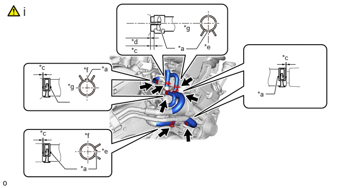
*a Paint Mark *b 210°
*c 2 to 5 mm (0.079 to 0.197 in.) *d 0 to 3 mm (0 to 0.118 in.)
*e Front Side *f Upper Side
*g RH Side - -


i.

Install the 7 water by-pass hose to the water inlet assembly and slide the hose clip to secure it.

NOTICE:
·

Align the hose and the hose clip at the locations shown in the illustration and install them.

·

Make sure the 7 water by-pass hose is securely inserted to the stopper.


Hide 17360G 6.CONNECT AIR TUBE ASSEMBLY (w/ Secondary Air Injection System)

Z101186

Click here(Click here)