1GR-FE INTAKE / EXHAUST INTAKE MANIFOLD INSTALLATION
CAUTION / NOTICE / HINT
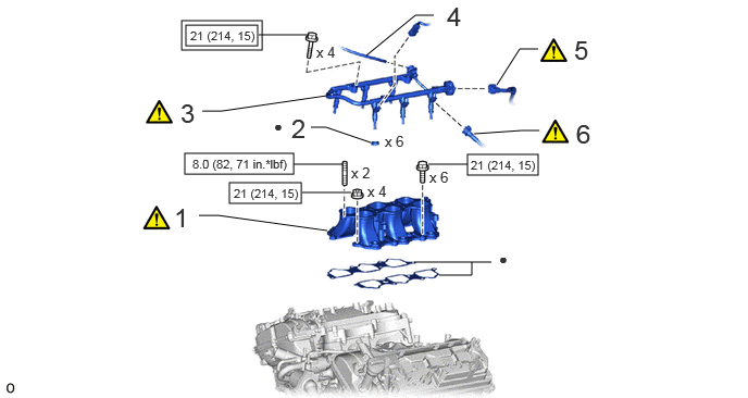
| Procedure | Part Name Code |

|

|

|
|
|---|---|---|---|---|---|
| 1 | INTAKE MANIFOLD | 17111 | ( ) |
- | - |
| 2 | INJECTOR VIBRATION INSULATOR | 23291 | - | - | - |
| 3 | FUEL DELIVERY PIPE SUB-ASSEMBLY | 23807 | () |
- | - |
| 4 | VACUUM TRANSMITTING HOSE ASSEMBLY | 25760 | - | - | - |
| 5 | NO. 2 FUEL PIPE SUB-ASSEMBLY | 23802B | () |
- | - |
| 6 | NO. 1 FUEL PIPE SUB-ASSEMBLY | 23801P | () |
- | - |

|
Tightening torque for "Major areas involving basic vehicle performance such as moving/turning/stopping": N*m (kgf*cm, ft.*lbf) |

|
N*m (kgf*cm, ft.*lbf): Specified torque |
| ● | Non-reusable part | - | - |
| Procedure | Part Name Code |
|
|
|
|
|---|---|---|---|---|---|
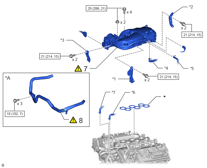
| 7 | INTAKE AIR SURGE TANK | 17129 | () |
- | - |
| 8 | AIR TUBE ASSEMBLY | 17360G | () |
- | - |
| *A | w/ Secondary Air Injection System | - | - |
| *1 | NO. 1 SURGE TANK STAY | *2 | NO. 2 SURGE TANK STAY |
| *3 | THROTTLE BODY BRACKET | *4 | NO. 1 VENTILATION HOSE |
| *5 | NO. 1 FUEL VAPOR FEED HOSE | *6 | NO. 4 WATER BY-PASS HOSE |
| *7 | NO. 5 WATER BY-PASS HOSE | - | - |
|
|
N*m (kgf*cm, ft.*lbf): Specified torque | ● | Non-reusable part |
| Procedure | Part Name Code |
|
|
|
|
|---|---|---|---|---|---|
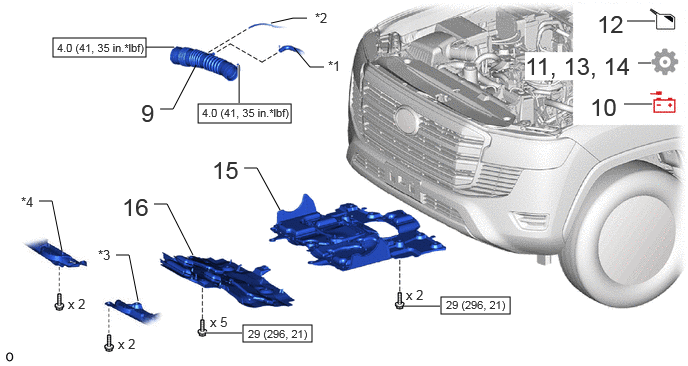
| 9 | AIR CLEANER HOSE ASSEMBLY | 17880 | () |
- | - |
| 10 | CONNECT CABLE TO NEGATIVE BATTERY TERMINAL | - | - | - | - |
| 11 | INITIALIZATION AFTER RECONNECTING BATTERY TERMINAL | - | - | - | () |
| 12 | ADD ENGINE COOLANT | - | - | () |
- |
| 13 | INSPECT FOR COOLANT LEAK | - | - | - | () |
| 14 | INSPECT FOR FUEL LEAK | - | - | - | () |
| 15 | NO. 2 ENGINE UNDER COVER ASSEMBLY | 51420 | - | - | - |
| 16 | NO. 1 ENGINE UNDER COVER ASSEMBLY | 51410 | - | - | - |
| *1 | VENTILATION HOSE | *2 | VACUUM HOSE |
| *3 | ENGINE SIDE COVER SUB-ASSEMBLY LH | *4 | ENGINE SIDE COVER SUB-ASSEMBLY RH |
|
|
N*m (kgf*cm, ft.*lbf): Specified torque | - | - |
PROCEDURE

 17111 1.INSTALL INTAKE MANIFOLD
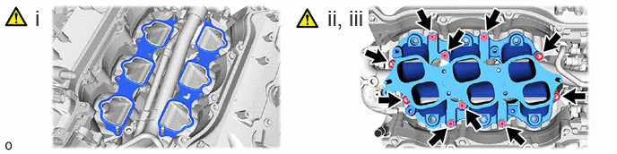
Set 2 new gaskets on each cylinder head.
- NOTICE:
-
·
Align the port holes of the gasket and cylinder head.
·Make sure the gaskets are installed facing the proper direction.
Set the intake manifold on the cylinder heads.
Install and uniformly tighten the 6 bolts and 4 nuts in several passes.
- Torque:
- 21 N*m (214 kgf*cm, 15 ft.*lbf)
- NOTICE:
-
Tighten the center installation bolts of the intake manifold before tightening the outer bolts and nuts.
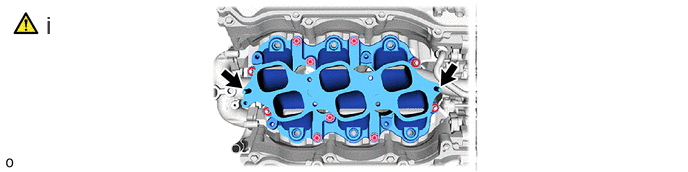
Using an E7 "TORX" socket wrench, install the 2 stud bolts to the intake manifold.
- Torque:
- 8.0 N*m (82 kgf*cm, 71 in.*lbf)
- NOTICE:
-
If a stud bolt is deformed or its threads are damaged, replace it.
23291 2.INSTALL INJECTOR VIBRATION INSULATOR
23807 3.INSTALL FUEL DELIVERY PIPE SUB-ASSEMBLY
|
|
Click here() |
25760 4.CONNECT VACUUM TRANSMITTING HOSE ASSEMBLY
23802B 5.CONNECT NO. 2 FUEL PIPE SUB-ASSEMBLY
|
|
Click here() |
23801P 6.CONNECT NO. 1 FUEL PIPE SUB-ASSEMBLY
|
|
Click here() |
17129 7.INSTALL INTAKE AIR SURGE TANK
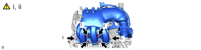
Install a new gasket to the intake air surge tank.
Install the intake air surge tank with the 4 bolts and 2 nuts in the order shown in the illustration.
- Torque:
- 28 N*m (286 kgf*cm, 21 ft.*lbf)
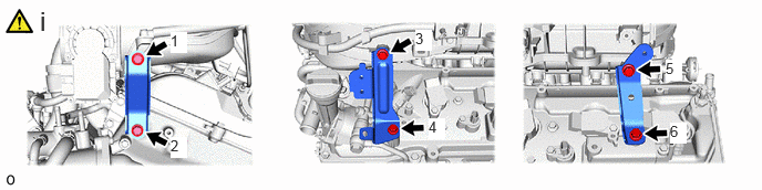
Install the throttle body bracket, No. 1 surge tank stay and No. 2 surge tank stay with the 6 bolts in the order shown in the illustration.
- Torque:
- 21 N*m (214 kgf*cm, 15 ft.*lbf)
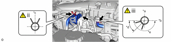
| *a | Front Side | *b | RH Side |
| *c | Upper Side | *d | 45° |
| *e | 180° | - | - |
Connect the connector and attach the wire harness clamp.
Connect the fuel vapor feed hose to the purge VSV, and slide the clip to secure the hose.
- NOTICE:
-
Align the hose clip at the locations shown in the illustration.
Connect the No. 1 PCV hose to the intake air surge tank, and slide the clip to secure the hose.
- NOTICE:
-
Align the hose clip at the locations shown in the illustration.
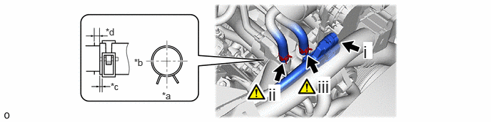
| *a | Front Side | *b | RH Side |
| *c | 2 mm (0.0787 in.) or higher | *d | 0 to 3 mm (0 to 0.118 in.) |
Connect the throttle body with motor connector.
Connect the No. 5 water by-pass hose to the throttle body with motor assembly, and slide the clip to secure the hose.
Connect the No. 4 water by-pass hose to the throttle body with motor assembly, and slide the clip to secure the hose.
17360G 8.INSTALL AIR TUBE ASSEMBLY (w/ Secondary Air Injection System)
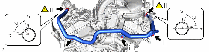
| *a | Upper Side | *b | RH Side |
| *c | LH Side | *d | 60° |
Install the air tube assembly with the 3 bolts.
- Torque:
- 10 N*m (102 kgf*cm, 7 ft.*lbf)
Connect the air tube assembly to the No. 1 emission control valve set and No. 2 emission control valve set, and slide the hose clip to secure it.
- NOTICE:
-
Align the hose clip at the locations shown in the illustration.
17880 9.INSTALL AIR CLEANER HOSE ASSEMBLY
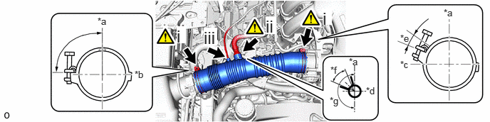
| *a | Upper Side | *b | Front Side |
| *c | Rear Side | *d | RH Side |
| *e | 15° | *f | 45° |
| *g | 180° | - | - |
Install the air cleaner hose with the 2 hose clamps.
- Torque:
- 4.0 N*m (41 kgf*cm, 35 in.*lbf)
- NOTICE:
-
Align the hose clamp at the locations shown in the illustration.
Connect the ventilation hose and slide the hose clip to secure it.
- NOTICE:
-
Align the hose clip at the locations shown in the illustration.
Connect the vacuum hose.
10.CONNECT CABLE TO NEGATIVE BATTERY TERMINAL
11. INITIALIZATION AFTER RECONNECTING BATTERY TERMINAL
Click hereGeneral>SETUP>WHEN DISCONNECTING OR RECONNECTING BATTERY TERMINAL>WORK PROCEDURE
- HINT:
-
When disconnecting and reconnecting the battery, there is an automatic learning function that completes learning when the respective system is used.
-
Click hereGeneral>SETUP>WHEN DISCONNECTING OR RECONNECTING BATTERY TERMINAL>AUTOMATIC LEARNING CHART
12.ADD ENGINE COOLANT
13.INSPECT FOR COOLANT LEAK
14.INSPECT FOR FUEL LEAK
51420 15.INSTALL NO. 2 ENGINE UNDER COVER ASSEMBLY
51410 16.INSTALL NO. 1 ENGINE UNDER COVER ASSEMBLY